6 7MAXDATA PLATINUM 100 I M9Setting up the System
Connecting the System
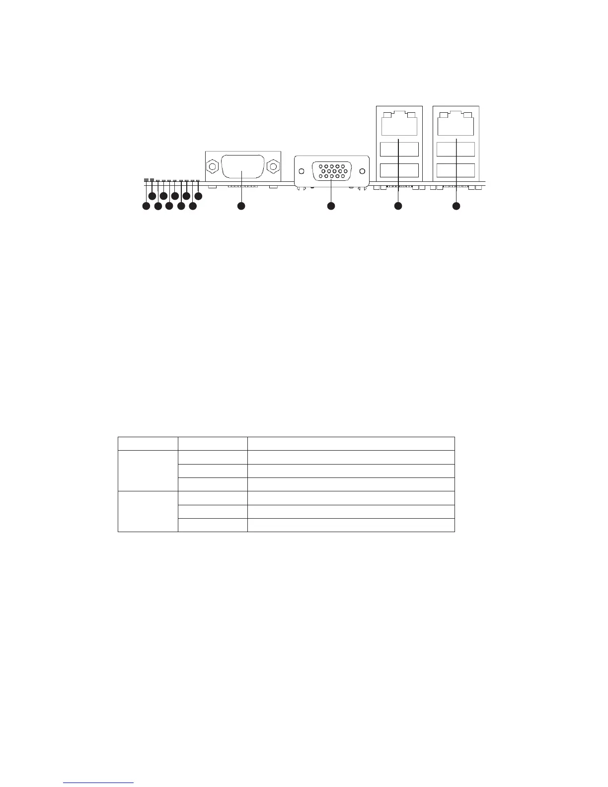
Back Panel Connectors
Figure 1. Back Panel Connectors
A. System Identification LED H. Diagnostic LED 2
B. Status LED I. Diagnostic LED 1
C. Diagnostic LED 7 (MSB LED) J. Diagnostic LED 0 (LSB LED)
D. Diagnostic LED 6 K. Serial Port A
E. Diagnostic LED 5 L. Video Port
F. Diagnostic LED 4 M. NIC 1 (top, default management port),
two USB ports (bottom)
G. Diagnostic LED 3 N. NIC 2 (top), two USB ports (bottom)
The NIC LEDs at the right and left of each NIC provide the following information.
Table 1. NIC LEDs
LED LED State Description
Left Off No network connection
Solid Green Network connection in place
Blinking Green Transmit/receive activity
Right Off 10 Mbps connection (if left LED is on or blinking)
Solid Green 100 Mbps connection
Solid Amber 1000 Mbps connection