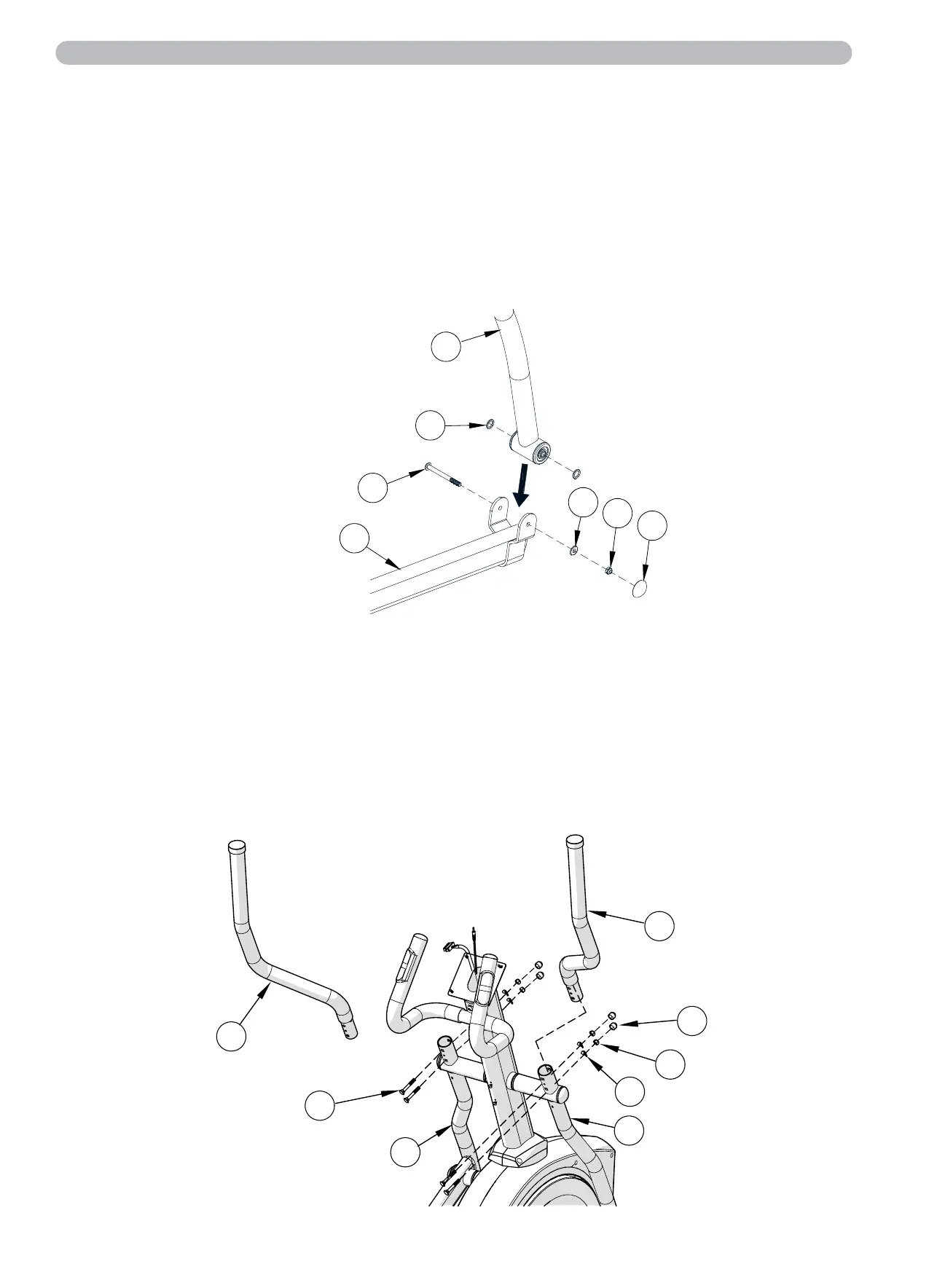
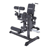
Step 11: Assembling the Side Handles
Position the right handle (A14) into the receptacle of the right swing arm (A04).
Secure the handle (A14) using two carriage bolts M8x50 (7), two curved washers M8x20x1.5 (6), and two lock
nuts M8 (14).
Place one nut cap (C17) on each of the nuts (14) for a finished appearance.
Repeat the same process with the left handle (A13). You can easily identify both side handles using
the corresponding stickers.
Step 10:
Repeat steps 6, 7, 8, and 9 on the left side of the device.
Assembly
Step 9: Assembling the Joint Connection of the Pedal Tube to the Swing Arm
Loosen and remove the pre-assembled screw (B24), washer (B33), and nut (B29) from the front mount of
the pedal tube (A06).
Connect the swing arm (A04) to the pedal tube (A06). Use the previously loosened screw (B24), washer (B33),
and nut (B29). Ensure that the two washers (C22) are correctly attached to the swing arm (A04).
Place the round screw covers (C11) on the nut (B29).
CAUTION:
When tightening the screw (B24) during the assembly of the joint connection between the swing arm (A04) and
the pedal tube (A06), ensure that the joint has optimal freedom of movement. Over-tightening the screw (B24)
can cause joint connection to become blocked during training. This can be indicated by a clicking noise when
both pedals are at the same height during training. If you notice this clicking noise, it is necessary to slightly
loosen the screw (B24).
A04
C22
B24
A06
B33
B29
C11
A13
A14
A03
7
C17
14
6
A04
10