Adjustable footAdjustable foot
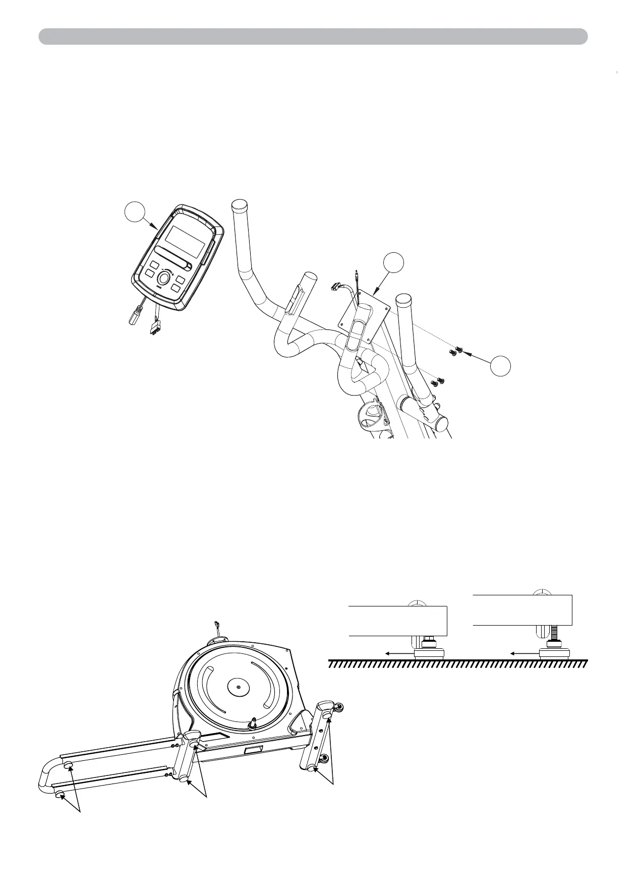
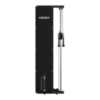
Step 14: Assembling the Cockpit
Loosen and remove the four pan head screws (B17) pre
assembled on the back of the cockpit. Connect the cables protruding
from the cockpit (D02) with the cables that protrude from the fixed
handlebars.
Please note that the cables can be easily identified by their connections.
Now fix the cockpit (D02) to the cockpit bracket on the handlebar stem (A02) with four previously loosened pan-head screws (B17).
ATTENTION:
Make absolutely sure that you do not pinch or damage the cables during assembly.
Step 15: Levelling the Device
Make sure your exercise equipment is always level. In order to compensate for minor bumps or slopes in t
he floor, adjustable feet are fitted on the right and left of the front and rear stands and on the sliding frame.
To make sure the position of the device is level, first turn all feet to the lowest position (position A). If necessary,
adjust the feet until the device is level and stable.
If the adjustment range of the levelling feet is not enough to allow the training device to stand safely, please
check the surface of the location and, if necessary, choose a different location, where a safe and level position
can be ensured.
Position A
Position B
Assembly
B17
A02
D02
Adjustable foot
Adjustable foot
Adjustable foot
12