PAGE 17
14. Replace the drive.
a. Reconnect harness and ground connection,
if separate. Reassemble all parts and panels.
b. Plug in washer or reconnect power.
Perform Service Diagnostics to verify repair.
If the motor still fails to operate,
go to step 15.
15. If the tests above have failed to fix motor
drive issues, replace the main control.
a. Unplug washer or disconnect power.
b. Replace the main control assembly.
c. Plug in washer or reconnect power.
Perform Service Diagnostics to verify repair.
TEST #4: Keys and Encoders
Keys and Encoders Test:
This test is performed when any of the
following situations occurs during “Key
Activation & Encoder Test” on page 3.
3One or more indicators do not light up
3Some buttons do not toggle indicators
3No audio feedback is heard
One or more indicators do not light up:
1. Unplug washer or disconnect power.
2. Access the console’s electronic assemblies
and visually check that the ACU J18 and
UI J17 connectors are inserted all the way
into the main control and that the UI harness
connector is fully seated on the UI. If the
speaker connector is visible, visually verify
that the speaker connects to J6 on the UI.
3. If both visual checks pass, follow procedure
under TEST #1, “Main Control” on page 14
to verify supply voltages.
4. Verify the continuity of the UI harness.
4. Remove console to access main control.
5. Visually check that the J1 connector is
inserted all the way into the main control.
If visual checks pass, go to step 6.
If visual checks fail, reconnect J1 and
repeat step 1.
6. With an ohmmeter, verify resistance values
as shown below:
7. Tilt washer back to access the bottom
of the washer and the drive motor area (see
Figure 3a, page 16).
8. Visually check that the motor connection
on the drive is fully inserted into its mating
connector.
If visual checks pass, go to step 9.
If visual checks fail, reconnect motor
connector on drive plate and repeat step 1.
9. With an ohmmeter, check for continuity on
the motor harness between all pins on the J1
machine/motor control connector and the drive
motor connector.
If there is continuity, go to step 10.
If there is no continuity, replace the
lower washer harness and run Service
Diagnostics to verify repair.
10. Tilt washer back (if it is not already) to
disconnect the motor connector and use an
ohmmeter to verify the motor resistance values
at the drive motor connector (see Figure 3b,
page 16).
11. Remove the motor bolt, then the motor
cover (see Figure 3b, page 16).
12. Remove the shifter coil and stator to
access the motor connection.
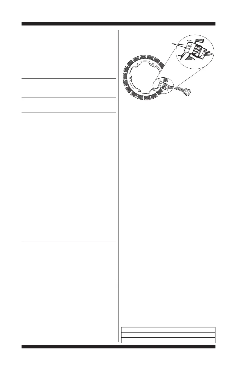
13. Visually check that motor electrical
connection cover is fully seated (see Figure 5).
If visual check passes, go to step 14.
If visual check fails, fully seat the motor
connection cover, reassemble stator and
motor cover, and repeat step 1.
Check Go to Go to
between Resistance Step 7 Step 10 Go to
connector value if values if values Step 10
pins should be: are: are: if:
J1 1–3 8–10 Ω Much Much Resistances
3–4 8–10 Ω higher than less than are all
10 Ω 8 Ω correct
Figure 5 - Removing Shifter Coil and
Checking Motor Electrical Connection
Motor Electrical
Connection Cover
(verify that clips are
fully seated)
Check
between Go to Go to
drive Resistance Step 11 Step 14 Go to
motor value if values if values Step 15
connector should be: are: are: if:
2–3 (R–BR) 8–10 Ω Much Much Resistances
3–4 (BR–BK) 8–10 Ω higher than less than are all
10 Ω 8 Ω correct
ACU J18 – Pin 1 Black
ACU J18 – Pin 2 Blue
UI J17 – Pin 3
UI J17 – Pin 2



 To Next Page