PAGE 14
FOR SERVICE TECHNICIAN’S USE ONLY
DO NOT REMOVE OR DESTROY
NOTE: On the gas dryer, the inlet thermistor
is located below the CCU bracket at the drum
inlet vent. Refer to strip circuit on page 22 to
diagnose heater system.
Dryer does not heat:
Locate the components using figures 20a and
20b. To access heater system components, see
Dryer Disassembly Instructions, page 24.
ELECTRIC DRYER ONLY:
3Quick Check: Perform the “CCU Line
Voltage 1” check under Component
Activation. If L1 is present, the heater relay
is receiving L1 line voltage.
3Quick Check: Perform the “CCU Line
Voltage 2” check under Component
Activation. If L2 is present, the heater relay
is receiving L2 line voltage, confirming that
the centrifugal switch, heater, high limit
thermostat, and the thermal cut-off are
functional.
1. Unplug dryer or disconnect power.
2. Remove front panel to access thermal
components.
3. Using an ohmmeter and referring to the strip
circuit or wiring diagram, measure the resistance
from the red wire terminal at the thermal cut-off
to the red wire terminal at the heater.
If the resistance is about 10 Ω, go to
step 5.
If an open circuit is detected, or resistance
is much greater or less than 10 Ω, go to
step 4.
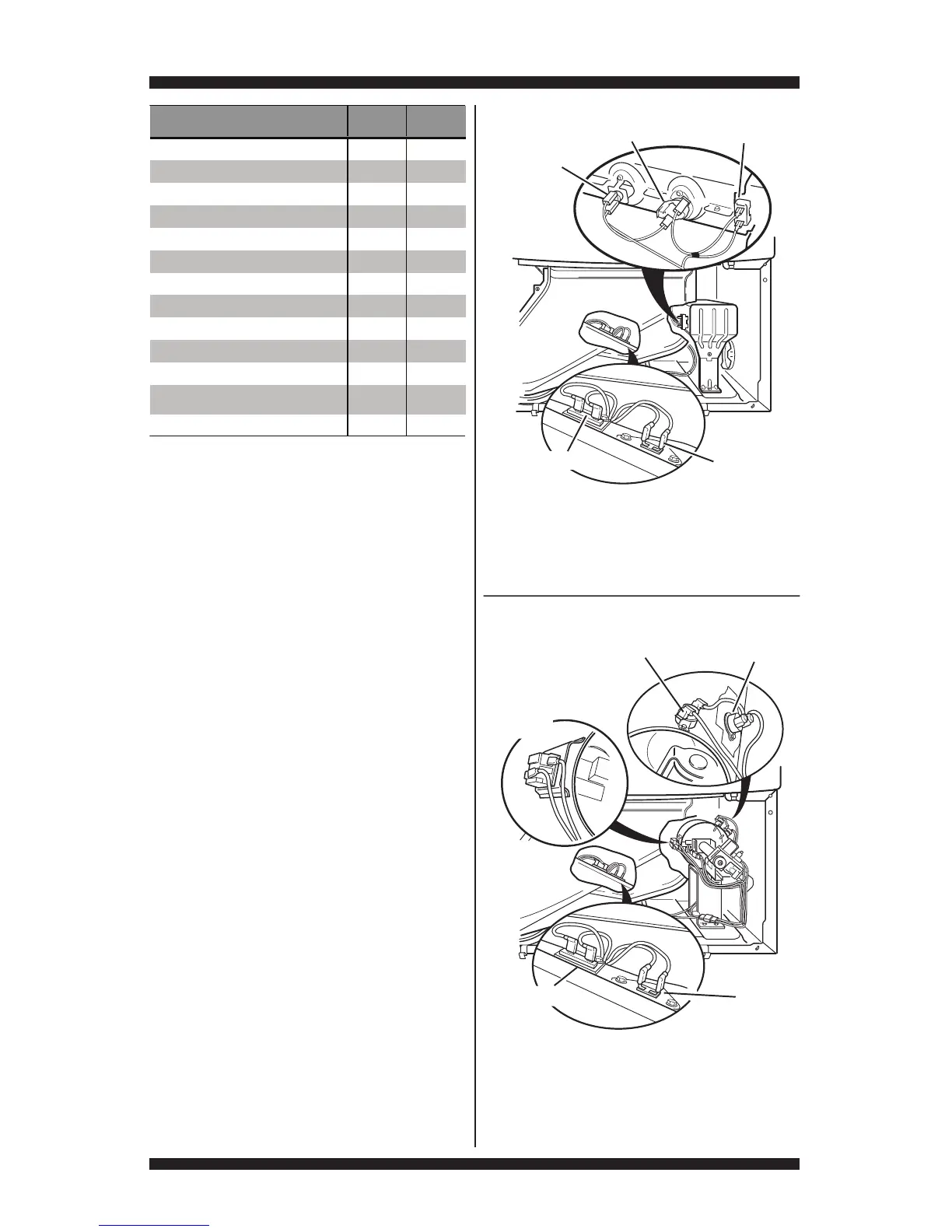
Figure 20b - Gas thermal components,
viewed from front.
Outlet
Thermistor
Thermal Fuse
Gas Dryer
Thermal
Cut-Off
High Limit Thermostat
Flame
Sensor
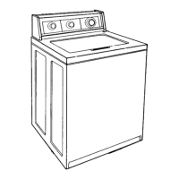
Figure 20a - Electric thermal components,
viewed from front.
Inlet Thermistor/High Limit
Thermostat Assembly
Heater
Element
Electric Dryer
Thermal Fuse
Outlet
Thermistor
Thermal
Cut-Off
Part of Heating System
Electric
Dryer
Gas
Dryer
Harness/connection