PAGE 23
FOR SERVICE TECHNICIAN’S USE ONLY
DO NOT REMOVE OR DESTROY
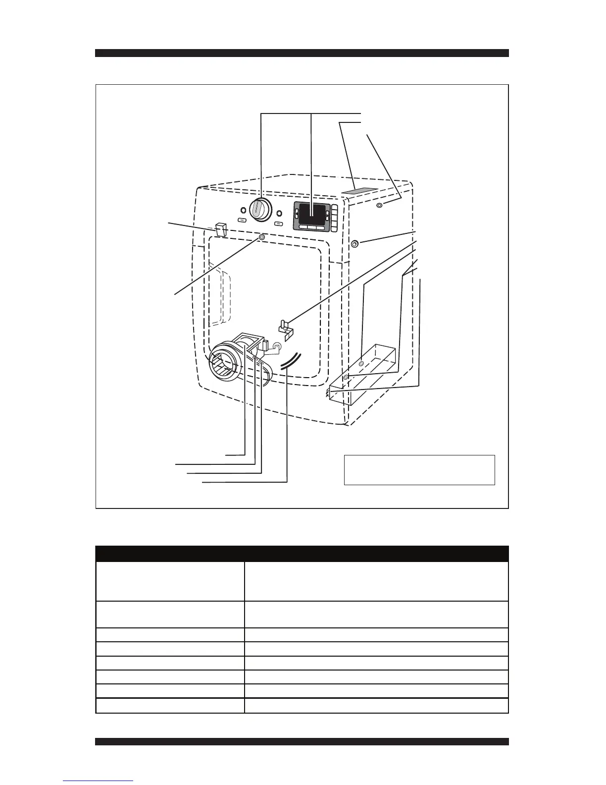
COMPONENT LOCATIONS
See Removing Top Panel, page 24, to access:
• User Interface (UI)
• Cycle Control Unit (CCU)
• Inlet Thermistor (Gas)
See Removing Rear Panel,
page 24, to access:
• Water Nozzle
• Water Valve
• Thermal Cut-off
• Inlet Thermistor (Electric)
• High Limit Thermostat
• Heater Assembly
Drum Light
Assembly
Door Switch
(Location may vary
between models)
See Removing Front Panel
and Bulkhead, page 24, to access:
• Motor Assembly & Belt Switch
• Thermal Fuse
• Outlet Thermistor
• Moisture Sensor Strips
Figure 25 - Component locations.
SPECIFICATIONS
Voltage:
240 V AC (200-260) Elect. Dryer, 2-phase, “optimized”
208 V AC (176-229) Elect. Dryer, 3-phase, “less optimized”
120 V AC (100-130) Gas Dryer
Amps:
(ELECT) 30 Amp Service
(GAS) 15 Amp Service
Frequency: 58 to 62 Hz (60 Hz nominal)
Water Pressure: 20-120 PSI
Operating Temperature Range: 40 to 105°F (5 to 40°C)
Dryer Height: 39 in. (99.1 cm)
Dryer Width: 27 in. (68.6 cm)
Dryer Depth: 31 in. (78.7 cm)
DRYER SPECIFICATIONS
NOTE: Refer to Figure 20b, page 14,
for gas dryer component locations.