4
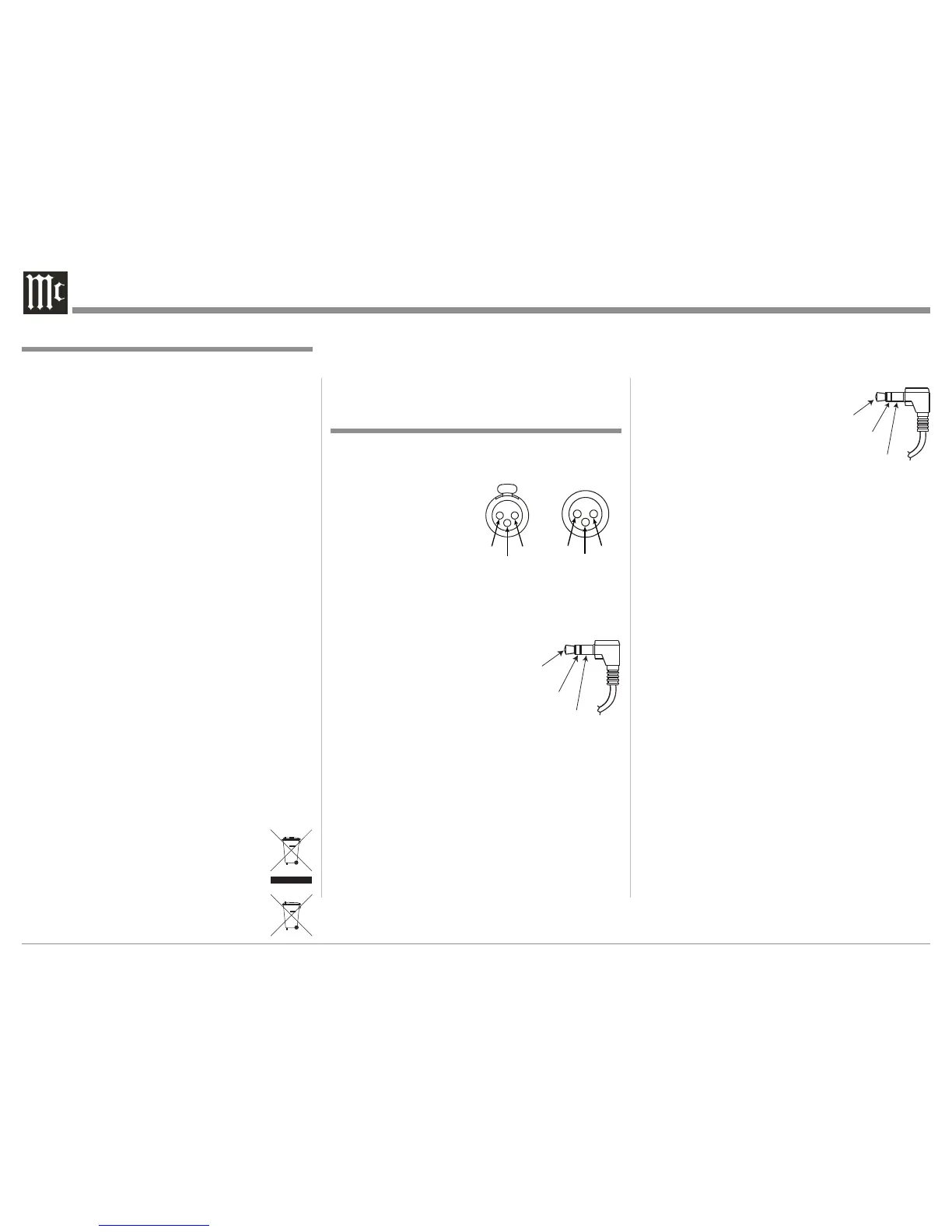
Data Port Connectors
The C50 Data Out Ports send Remote Control Signals
to Source Components. A 1/8
inch stereo mini phone plug is
used for connection.
General Information and Connector Information
Connector and Cable Information
XLR Connectors
Below is the Pin configuration for the XLR Balanced
Input and Output Connectors on the C50. Refer to the
diagrams for connections:
PIN 1: Shield/Ground
PIN 2: + Output
PIN 3: - Output
Power Control and Trigger Connectors
The C50 Power Control Out,
Trigger and Pass-Thru Out-
put Jacks send Power On/Off
Signals (+12 volt/0 volt) when
connected to other Components.
An additional connection is for
controlling the illumination of
the Power Output Meters on
McIntosh Power Amplifiers. A
1/8 inch stereo mini phone plug is used for connection
to the Power Control, Trigger and Pass-Thru Outputs
on the C50.
Note: The Power Control, Trigger, Pass-Thru and Data
Connecting Cable is available from the McIntosh
Parts Department:
Power Control, Trigger, Pass-Thru and Data
Cable Part No. 170-202
Six foot, shielded 2 conductor, with 1/8 inch stereo
mini phone plugs on each end.
1. For additional connection information, refer to the
owner’s manual(s) for any component(s) connected
to the C50 Audio Preamplifier.
2. The Main AC Power going to the C50 and any
other McIntosh Component(s) should not be applied
until all the system components are connected
together. Failure to do so could result in malfunc-
tioning of some or all of the system’s normal opera-
tions. When the C50 and other McIntosh Compo-
nents are in their Standby Power Off Mode, the
Microprocessor’s Circuitry inside each component
is active and communication is occurring between
them.
3. Balanced and Unbalanced Inputs and Outputs can
be mixed. For example, you may connect signal
sources to Unbalanced Inputs and send signals
from the Balanced Outputs. You can also use Bal-
anced and Unbalanced Outputs simultaneously,
connected to different Power Amplifiers.
4. The C50 internal Digital to Analog Converter
Circuitry is designed to decode 2-channel PCM
(Pulse Code Modulation) Digital Signal present at
the Coaxial and Optical Digital Audio Inputs. Other
Digital Audio Signal Format Types will cause the
Audio Outputs of the C50 to be muted and the Front
Panel Information Display will indicate an error
message.
5. The Remote Control Supplied with the C50 In-
tegrated Amplifier is capable of operating other
components. For additional information go to www.
mcintoshlabs.com.
6. When discarding the unit, comply with
local rules or regulations. Batteries should
never be thrown away or incinerated but
disposed of in accordance with the local
regulations concerning battery disposal.
General Information