SimStep Manual - 3400 Iss. D 7
th
June 2004 page 14
4.3 Connection of Limits And Datum
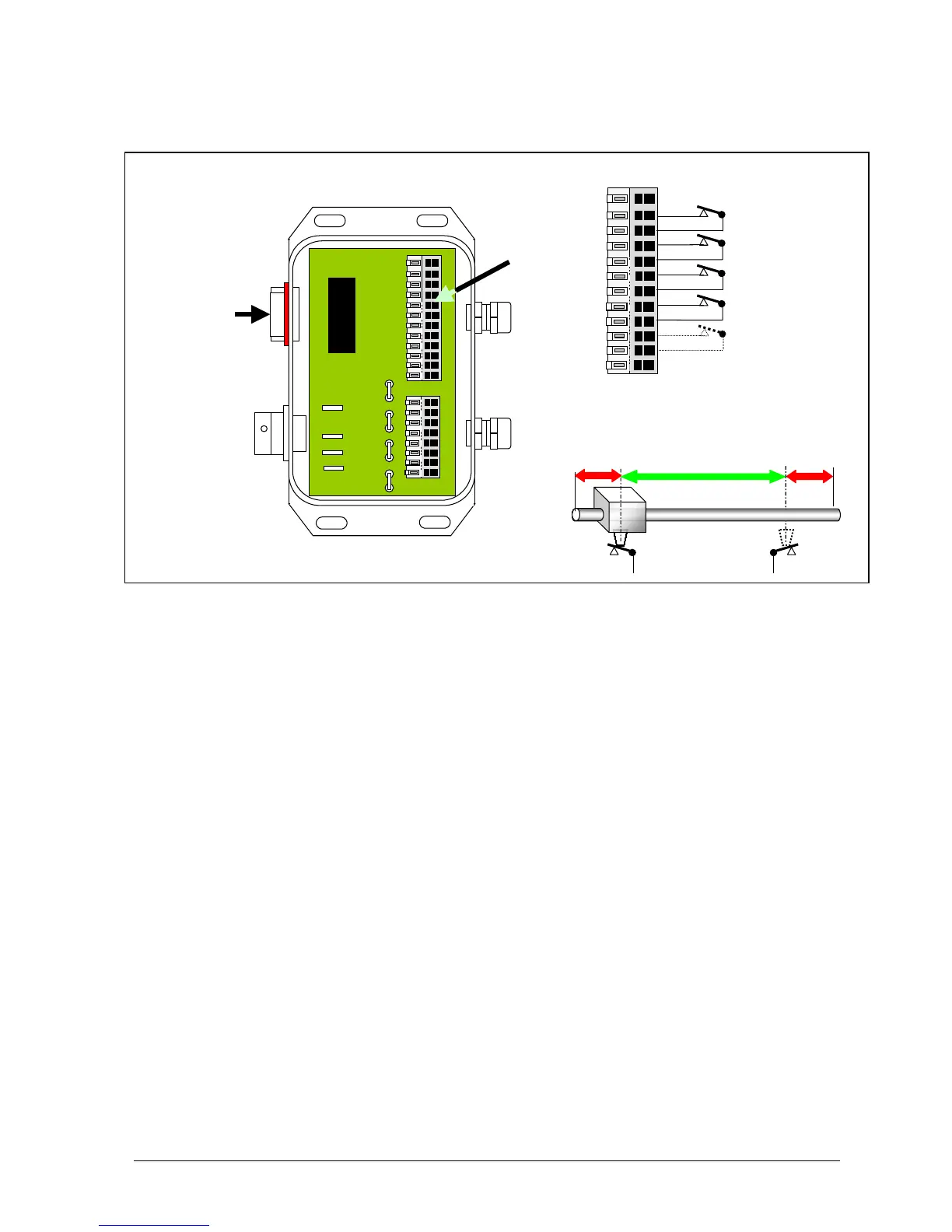
Fig. 4.5 Limit/Datum Connections
All limit and datum signal inputs should utilise normally closed contacts.
Note* The datum approach signal is not always required. This is the case when:
a) The motor is operated at slow (creep speed) since it is not necessary to
decelerate before stopping at the datum point. In this case the datum
approach terminals should not be connected.
b) When the controller is configured to utilise the high-speed datum registration
feature. In this case, the datum approach connections should be linked.
Note ** This connection enables an external open contact to abort a move. However
for this feature to be utilised it is necessary to remove an internal link LK8
within the controller.
It should be noted that the limit switches should be placed sufficiently within the total travel
distance to allow the motor to decelerate from high speed.
They should also be mounted for sliding operation, so that they do not become crushed on
first use. No mechanism can decelerate instantaneously.
Limit / datum connections
0VLL
+VLL +over-travel limit
Upper Limit
+VLL - over-travel limit
Lower Limit
Limits datum cable +VLL datum approach *
507LDCxx894 Datum App
+VLL datum stop
Datum stop
+VLL
Abort stop abort stop **
Allow sufficient deceleration over-travel
1’ deceleration deceleration
zone working zone zone
- Limit + Limit