SimStep Manual - 3400 Iss. D 7
th
June 2004 page 22
8 PM600 Intelligent Stepper Motor Controller
The PM600 is a microprocessor-based unit for controlling servo or stepper motors. The
controller has a wide range of functions available; these are described in detail in the
PM600 manual included with this documentation. The SimStep will operate under manual
control with either a jog box or joystick, or can run under remote control through the
RS232 (or RS485) interface.
Basic information on the command structure and the RS232 interface is given below; the
user should refer to the PM600 manual for complete details.
8.1 General
The PM600’s switches have been set as follows:
RS232 Control
The controllers are set to axis address 1
The baud rate is set to 9600 baud
The word mode is set to 7 bits, even parity
Quiet mode is selected
Rotary switches SW1 and SW2 set the axis address. These are set to the actual
address required. SW3 sets the communication configuration. For further information
refer to the Switch Setting section (10) of the PM600 manual
The control mode has been set to open-loop stepper mode by the command 1CM11.
When using the SimStep with an encoder, the control mode can be changed to
closed-loop stepper by the command 1CM14.
8.2 Setting Up The Encoder (Closed-loop Control Modes Only)
Each edge of the quadrature signals is counted, so the number of encoder counts per
revolution will be four times the line count of the encoder.
The PM600 can be used with encoder producing either 5V TTL signals or
5V line
driver
signals. The correct termination should be set. This gives maximum noise
immunity. The use of encoders with
line driver
type signals is recommended where the
encoder lead length will exceed 1m.
8.2.1 Encoder Termination
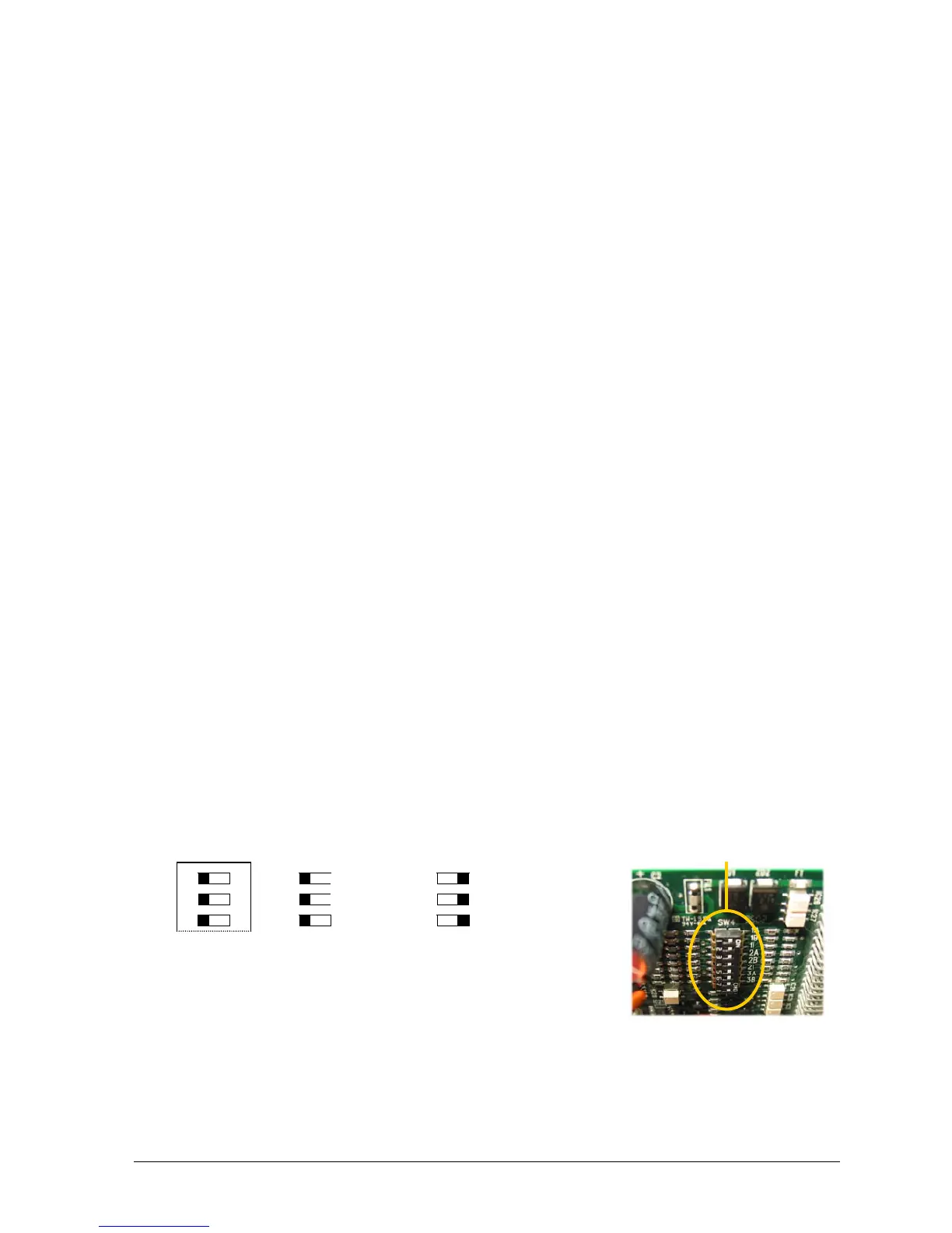
Switch SW4 selects the termination for the encoder signals. If using differential signals
then the encoder termination should be switched on. With 5V TTL encoders, the
encoder termination switches should be switched off.
1B
1I
1A
3
O
N
1
2
1
2
Single
ended
(TTL)
3
1
2
Line Driver
(Default)
3
Fig.8.1 Encoder Termination Configuration Switch SW4
SW4