SimStep Manual - 3400 Iss. D 7
th
June 2004 page 27
9.1 Isolation
The
Read Port
inputs and
Write Port
outputs are opto-isolated. A +24V nominal supply
must be used as the common for these inputs. This supply can either be a separate
external supply or the SimStep’s internal +24V supply. If the internal supply is used, then
the WP-com
terminal must be connected the +VLL terminal on the Breakout box and the
RP-com terminal must be connected the 0V
terminal on the Breakout box. If a separate
supply is used then the WP-Com terminal must be connected to the +24V
terminal of the
external power supply and the RP-Com terminal must be connected to the 0V
terminal of
the external power supply. The +24V output from the external supply can be used for the
common of the switches.
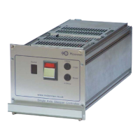
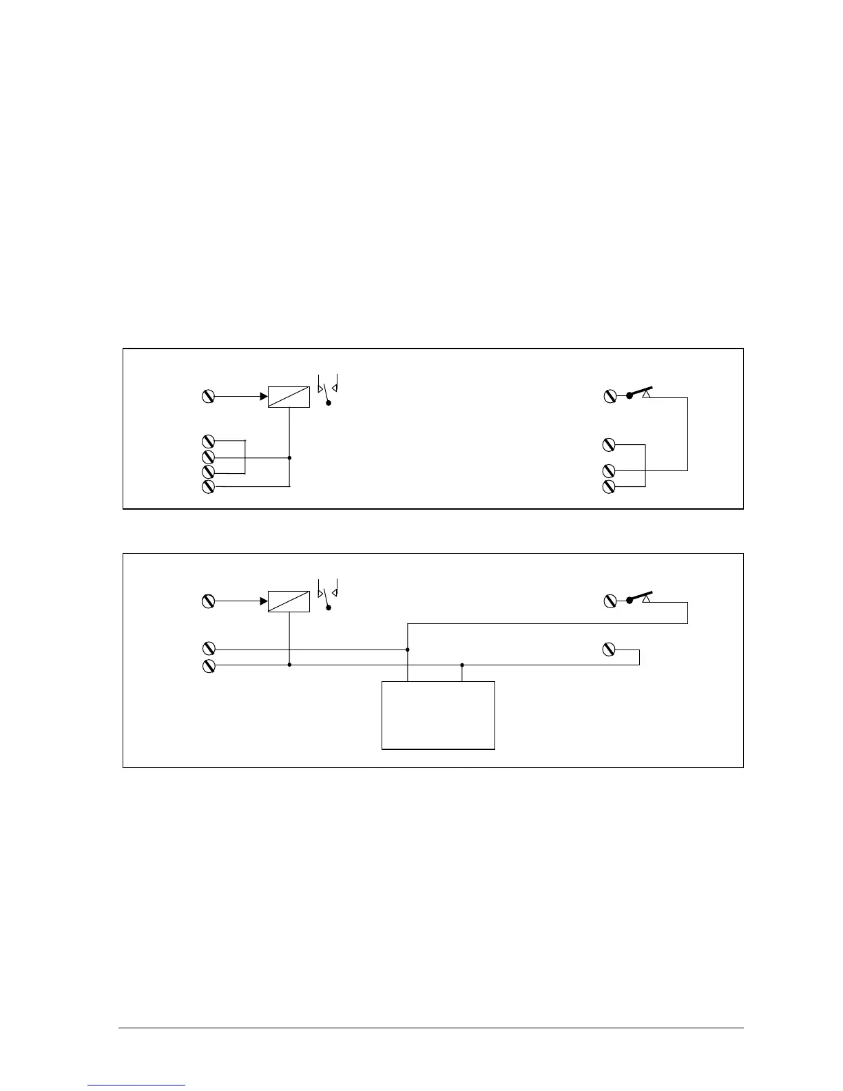
9.2 Typical Connections
Fig. 9.3 Typical Connections to the I/O Breakout Box
Fig. 9.4 Typical I/O Connections using an External Supply
9.3 Read Ports
The
read ports
can be connected to a PNP signal output, a switch, or another SimStep’s
write port
.
The RP Read input Port command is used to check the operation of the
read ports
. This
instruction returns an eight digit binary number of either 0 or 1 characters to represent the
current state of the read port. These start with
read port
8, through to 1. Referring to
figures 9.3 and 9.4, a 1 represents a closed switch and a 0 represents an open switch.
The input voltage that is considered as a logic 1 signal is 10-35V and the input voltage that
is considered as a logic 0 is 0-5V.
Typical Output Line Connections Typical Input Line connections
WP RP
Low current Relay
WP – com RP-com
Diode com
+VLL +VLL
0V 0V
Typical Output Line Connections Typical Input Line connections
+24V 0V
External
PSU
WP
Diode com
WP – com
RP-com
RP
Low current Rela