Section 2: Water Pipe Circuit
We have seen that the mini chiller has an integrated buffer storage tank, expansion tank and
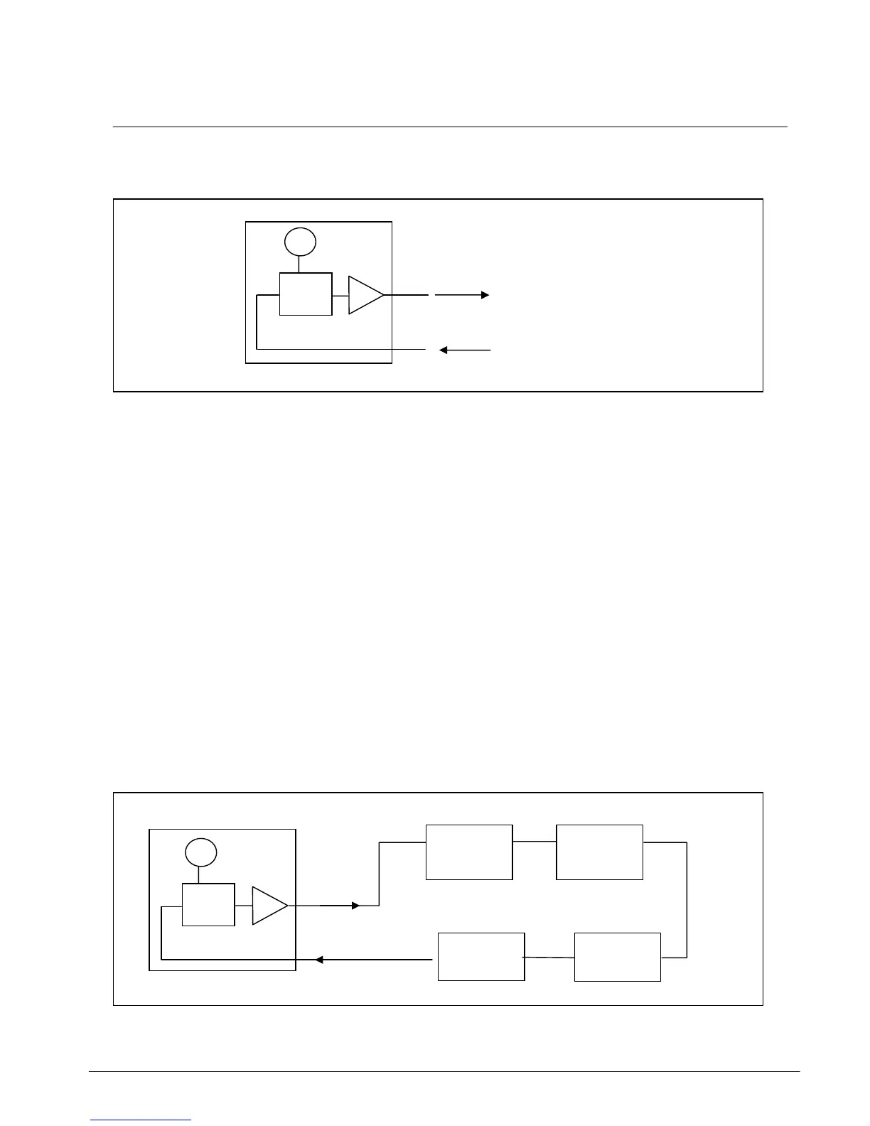
water pump together as one unit. Henceforth, we will represent the unit as such:
MINI CHILLER UNIT
In this section, we will look at the various piping circuits which we can use to connect the chiller
unit with the load fan coil units.
There are many different piping circuit configurations which can be used, depending on:
a) the geometry of the building
b) the available space for installation (e.g. the dimensions of the plant room)
c) the economics of installation
d) loading capability requirements
The general rule of thumb in designing and determining the piping circuit network is:
KEEP IT SIMPLE!
The more extensive a pipe network is, the more complex it is and it becomes more difficult to
analyse and control.
In general, there are 4 types of this pipe configuration:
1. Series
2. Diverting
3. Parallel direct return
4. Parallel reverse return
Series Circuit:
Note: For C-series, the buffer tank is not
applicable but the fundamentals of water piping
circuitry is still the same
Water out
Water in
LOAD
FCU 1
LOAD
FCU 4
LOAD
FCU 3
LOAD
FCU 2
Section 2 Page 9