Adjustments of the throttling valves (e.g. globe valves, balancing valves) are then made to
ensure sufficient flow rate through each chiller.
We can also measure the water temperature difference between the supply and return side of
each chiller to check if the balancing is sufficient or not. The correct result should be about 4 - 5
°C.
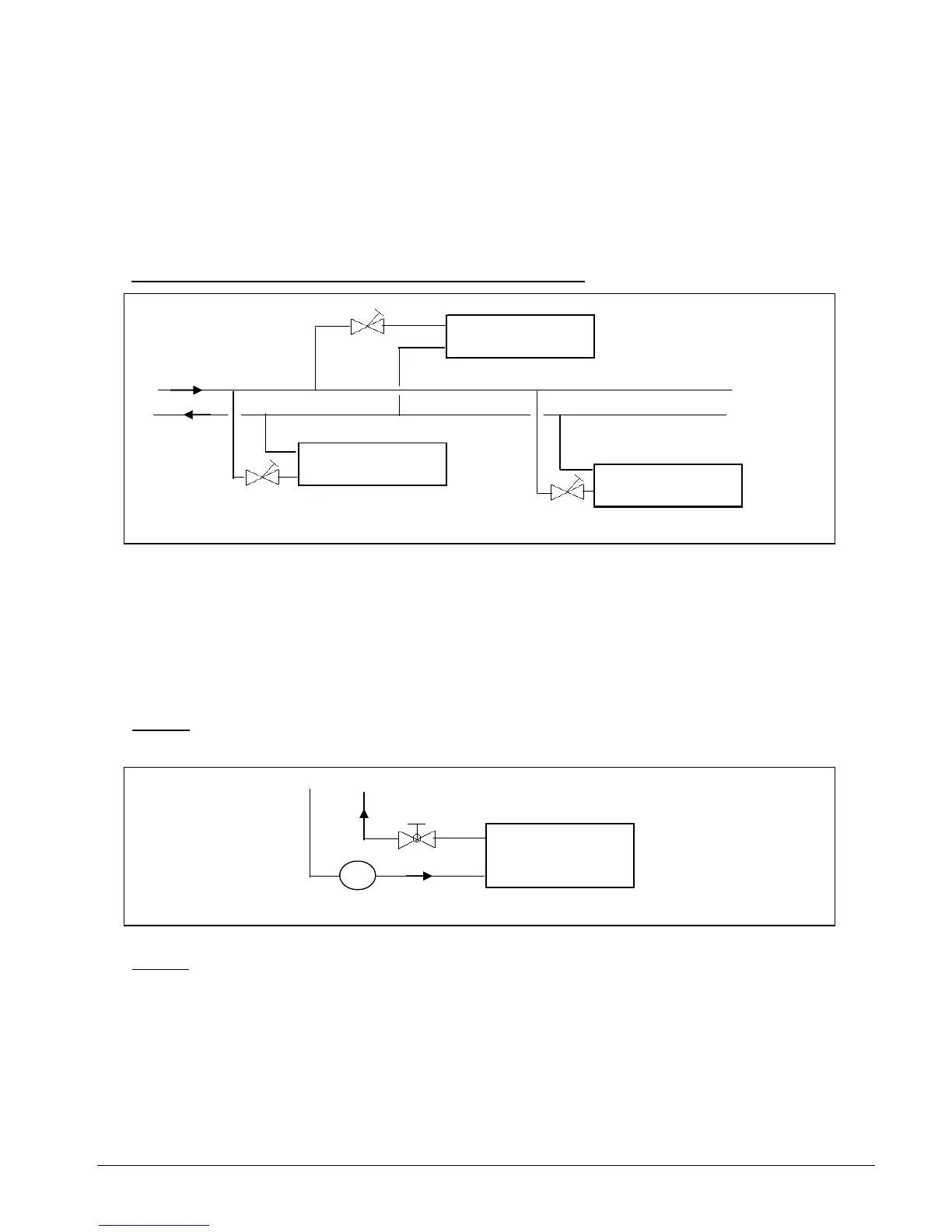
2. Multiple fan coil units: direct flowrate measurement
Supply
Return
balancing valve
FCU 1
FCU 3
FCU 2
To directly measure the flowrate, we need to install balancing valves into each of the fan coil
units. Each balancing valve will have an inlet and an outlet port to allow connection to a pressure
meter. By measuring this pressure drop across the valve itself, the flowrate can be determined by
using the valve calibration charts. See Appendix 18 for an example.
Compare these data with the design specifications. Adjust the balancing valves where necessary
to obtain the required flowrate.
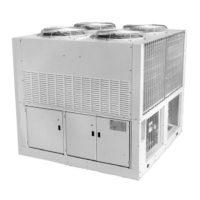
Note 1:
It is also possible to install a flowmeter along the supply line together with a globe valve,
to perform the same function as above. An orifice type flowmeter may be suitable in such case.
globe valve
Flowmeter
FCU
F
Note 2 : The balancing valves can also be installed for the multiple chillers as in example 1 above
to measure the flow rate.
Section 13 Page 147