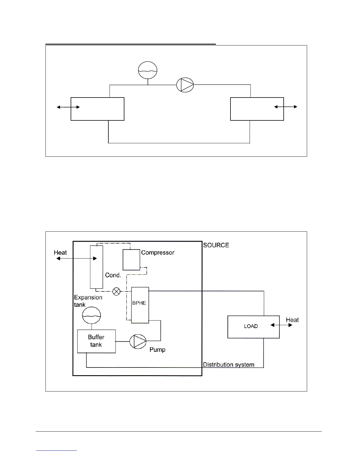
Schematic diagram of the basic close hydronic system:
Expansion
tank
Heat Pump Heat
Distribution system
SOURCE LOAD
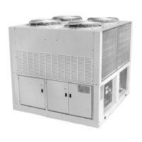
In the mini chiller, the source will comprise of the refrigeration circuit, i.e. compressor, expansion
device, condenser and evaporator. A brazed plate heat exchanger (BPHE) is used as the
evaporator to produce the chilled water.
A built-in water tank is also provided in the mini chiller to act as a buffer storage. See next page.
For integration, both the expansion tank and pump are incorporated together into the mini chiller.
Hence, the schematic diagram of the system becomes as follows:
Introduction Page 2