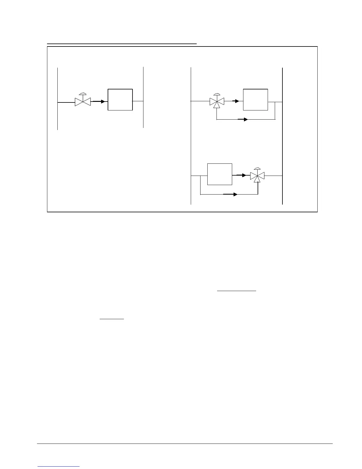
Capacity Control With 2-Way and 3-Way Valves
supply return supply ret
urn
The load of the fan coil unit can be calculated from the equation:
Q = 4180 * (water flow rate, L/s) * (water temperature differential.°C) Watt
th the 2- ay and 3- ay
alve will vary t
∆t".
LOAD LOAD
LOAD
diverting
mixing
Therefore, the load is propotional to the water flow rate and ∆t. Bo w w
v he flow rate to accomodate changes in the load demand.
With the 2-way valve, the system is considered as "variable flow, constant ∆t".
With the 3-way valve, the system is considered as "constant flow, variable
It is recommended that the 3-way valve to be configured as a diverting valve
instead of a mixing
valve. This is because when the fan coil unit is OFF, cold water will not enter into the heat
exchanger with the valve diverting the water away to the return line. Unlike the mixing valve, even
though the valve may be closed, cold water can still enter into the heat exchanger and ccumulate
there. As a result, sweating
on the heat exchanger and the connecting joints will occur even
the fan coil unit is not running.
However, on the o
when
ch valves, choosing instead the mixing configuration.
ther hand, 3-way diverting valves cost more than mixing valves. This is why
some designs do not call for su
Section 3 Page 48
 Loading...