For a given flow rate, we can select a valve with suitable C
v
to give an appropriate pressure
drop. These data are available in graphs provided by the manufacturer. See Appendix 5.
Selection of the valve must be done so as not to have too high a pressure drop, else the
water pump head will be insufficient for the system. The values of these valve pressure
drop can also be used during pump sizing. See Section 5.
For control valves (modulating, throttling duty, 2-way and 3-way), the pressure drop should
be no less than half the total pressure drop in the branch. This will allow a stable control.
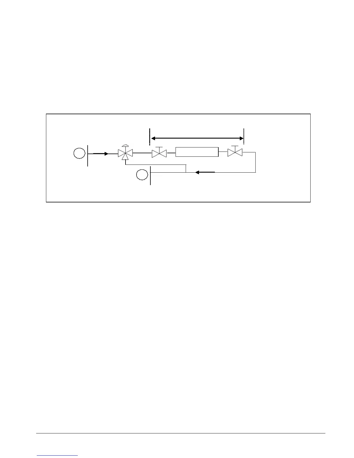
Example :
Pressure drop = 6 feet
FAN COIL UNIT
A
B
3-wa
supply
return
Pressure losses along piping works from A to B = 4.6 feet
Pressure drop across 2 gate valves + coil heat exchanger = 6 feet
Therefore, the control 3-way valve should have a pressure drop of at least
= 2 * (4.6 + 6)
= 21.2 feet
= 9.2 psi ** Conversion: 1 psi = 2.309 feet water
If the flow rate through the branch is 6 GPM, what valve C
v
should be used?
Refering to the graph in Appendix 5, the C
v
should be 2.
Therefore, a 3-way diverting valve with C
v
of 2 (at full opening) should be selected
for the above application.
As can be seen from the example above, the valve sizing was done with the design flow
at full opening. Thus, at reduced flows, the valve will close and this will increase the
pressure drop.
This can be seen from the following graph which depicts the system curve and pump
curve for a single fan coil load. See Section 5 for more details on pump curves.
Section 3 Page 59
 Loading...