18 AGZ 030A through 065A IOM 686
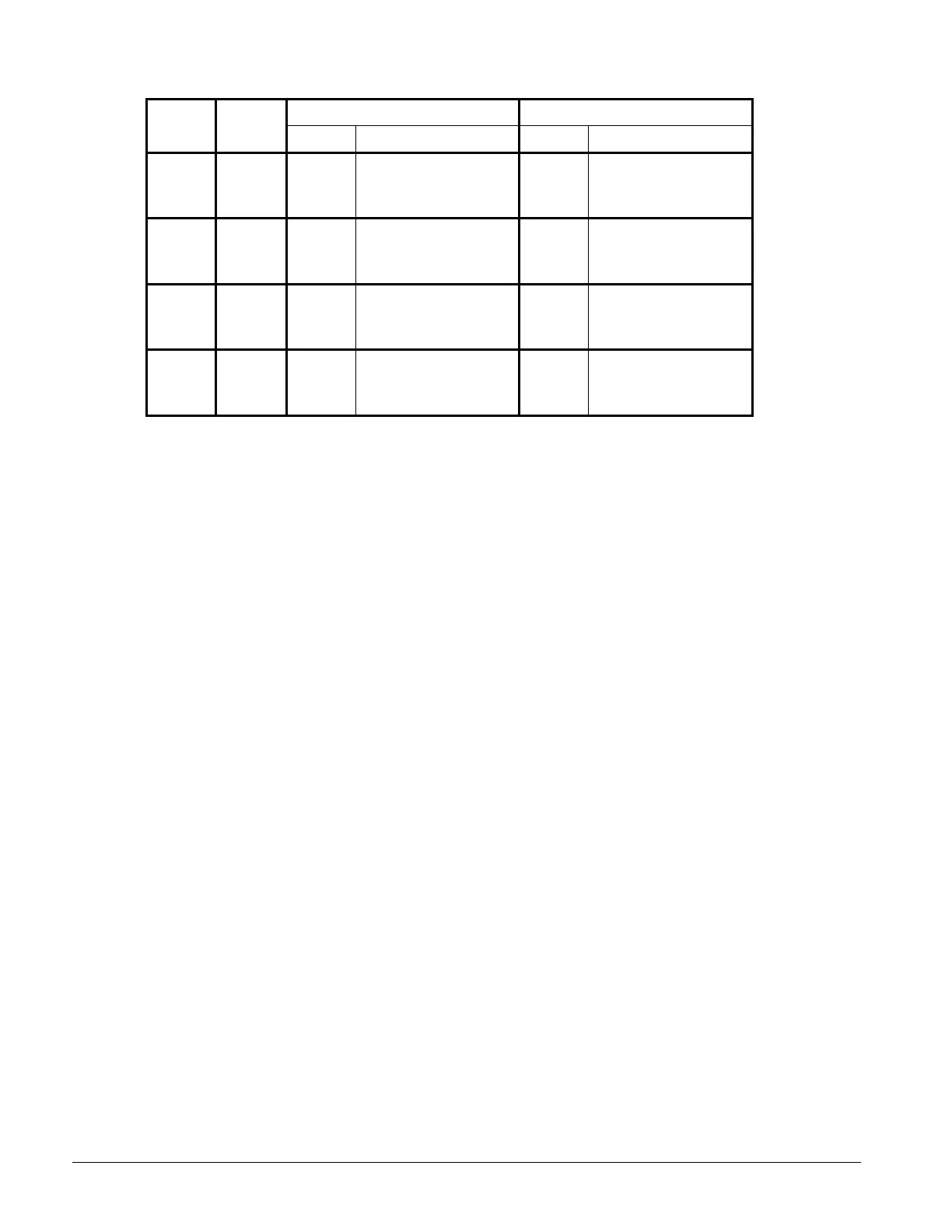
Table 12, AGZ030A - 065A, 60 Hz Single Point Power, Field Wiring Data (continued)
Wiring to Standard Wiring to Optional
AGZ Power Block Non-Fused Disconnect Switch
Unit Volts Terminal Connector Wire Range Terminal Connector Wire Range
Size Amps (Copper Wire Only) Amps (Copper Wire Only)
208 335 # 4 - 400 MCM 225 # 3 - 300 MCM
230 335 # 4 - 400 MCM 225 # 3 - 300 MCM
050AS 380 335 # 4 - 400 MCM 150 #4 - 4/0
050AE 460 175 #12 - 2/0 150 #4 - 4/0
575 175 #12 - 2/0 150 #4 - 4/0
208 335 # 4 - 400 MCM 400 250 - 500 MCM
230 335 # 4 - 400 MCM 400 250 - 500 MCM
055AS 380 335 # 4 - 400 MCM 250 #4 - 350 MCM
460 175 #12 - 2/0 150 #4 - 4/0
575 175 #12 - 2/0 150 #4 - 4/0
208 335 # 4 - 400 MCM 400 250 - 500 MCM
230 335 # 4 - 400 MCM 400 250 - 500 MCM
060AS 380 335 # 4 - 400 MCM 250 #4 - 350 MCM
460 175 #12 - 2/0 150 #4 - 4/0
575 175 #12 - 2/0 150 #4 - 4/0
208 335 # 4 - 400 MCM 400 250 - 500 MCM
230 335 # 4 - 400 MCM 400 250 - 500 MCM
065AS 380 335 # 4 - 400 MCM 250 #4 - 350 MCM
460 175 #12 - 2/0 150 #4 - 4/0
575 175 #12 - 2/0 150 #4 - 4/0
Notes for “Electrical Data Single Point” Power:
1. Unit wire size ampacity (MCA) is equal to 125% of the largest compressor-motor RLA plus
100% of RLA of all other loads in the circuit including the control transformer.
2. If the control transformer option is furnished, no separate 115v power is required.
3. If a separate 115V power supply is used for the control circuit, then the wire sizing amps is 10
amps for all unit sizes.
4. Recommended power lead wire sizes for 3 conductors per conduit are based on 100% conductor
ampacity in accordance with NEC. Voltage drop has not been included. Therefore, it is
recommended that power leads be kept short. All terminal block connections must be made with
copper (type THW) wire.
5. “Recommended Fuse Sizes” are selected at approximately 150% to 175% of the largest
compressor RLA, plus 100% of all other loads in the circuit.
6. “Maximum Fuse Sizes” are selected at approximately 225% of the largest compressor RLA, plus
100% of all other loads in the circuit.
7. The recommended power lead wire sizes are based on an ambient temperature of 86° F.
Ampacity correction factors must be applied for other ambient temperatures. Refer to the
National Electrical Code Handbook.
Voltage Limitations:
Within ± 10 percent of nameplate rating
Notes for “Compressor and Condenser Fan Amp Draw”:
1. Compressor RLA values are for wiring sizing purposes only but do not reflect normal operating
current draw at rated capacity. If unit is equipped with SpeedTrol condenser fan motors, the first
motor on each refrigerant circuit is a single phase, 1hp motor, with a FLA of 2.8 amps at 460
volts, 5.6 amps at 208, 230, 380, and 575 volts.
2. Compressor LRA for reduced inrush start are for the first winding only. If the unit is equipped
with SpeedTrol motors, the first motor is a single phase, 1 hp motor, with a LRA of 7.3 amps at
460 volts, 14.5 amps at 208, 230, 380, and 575 volts.
Notes for “Field Wiring Data”
1. Requires a single disconnect to supply electrical power to the unit. This power must be fused.
2. All field wiring to unit power block or optional non-fused disconnect switch must be copper.
3. All field wire size values given in table apply to 75° C rated wire per NEC.
 Loading...


