88 IOMM ACZ/AGZ-1
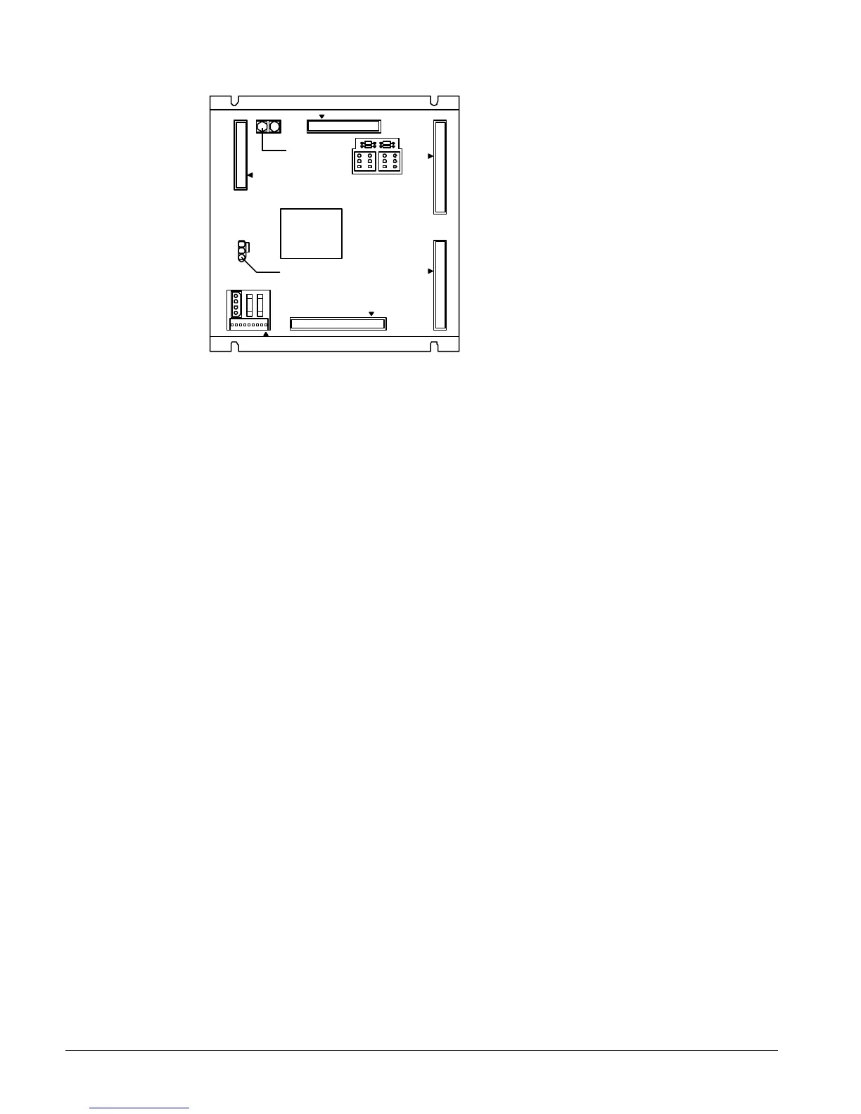
Figure 31, Microprocessor Control Board (MCB)
RUNNING
RESET
ACTIVE OUTPUT 0
CPU
STATUS
POWER FUSES
[BUSSMAN GDC-T2A]
POWER IN
[18-24 VCT]
AC AC GND GND
AUX/OUT
DIGITAL OUTPUTS
ANALOG INPUTS DIGITAL INPUTS
HI
ADDRESS
LO
KEYPAD/LCD DISPLAY
COMMUNICATIONS
PORT A PORT B
[FUSE: BUSSMAN MCR-1/4]
FUSE 1
2
3
4
Hex switches
Microprocessor status LED's
EXPANSION BUS
Digital Inputs Connection
The MCB receives digital inputs from the Analog Digital Input (ADI) board through the Digital Inputs
connector via a plug-in ribbon cable. The ADI board conditions these inputs.
Analog Inputs Connection
The MCB receives conditioned analog inputs from the ADI board through the Analog Inputs
connector via a plug-in ribbon cable. The ADI board conditions these inputs. After having been
conditioned, all analog inputs enter the MCB through the Analog Inputs port as 0–5Vdc signals.
Digital Outputs Connection
After processing all input conditions, the MCB sends the appropriate output signals to output
devices through the Digital Outputs port via a plug-in ribbon cable.
Power In Connector
The MCB receives 18Vac, center-tapped power from transformer T4 through the Power In connector.
This power drives all logic and communications circuitry.
Power Fuses
Two identical 2-amp fuses are located to the right of the Power In connector. These fuses are in the
MCB power supply circuit.
Microprocessor Status LEDs
The green, red, and amber LEDs on the MCB provide information about the operating status of the
microprocessor. The amber LED also indicates the existence of alarm conditions.
Following is the normal start-up sequence that the three status LED’s should follow when power is
applied to the MCB:
1. The red (“Reset”) LED turns on and remains on for approximately 5 seconds. During this period
the MCB performs a self-test.
2. The red LED turns off and the green (“Running”) LED turns on. This indicates that the
microprocessor has passed the self-test and is functioning properly.
3. The amber (“Active”) LED remains off continually if no alarm conditions exist in the network. If
alarm conditions exist, the amber LED will flash as shown in Table 5.
 Loading...