IOMM ACZ/AGZ-1 87
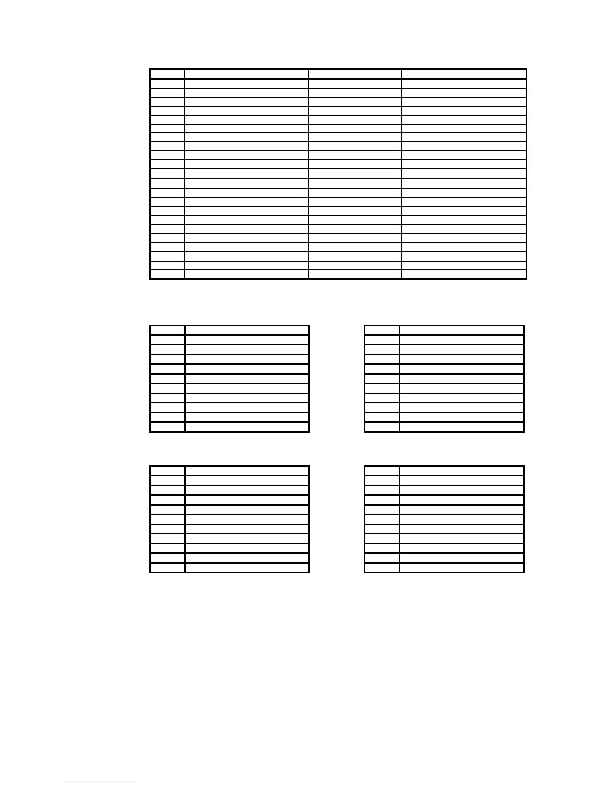
Table 51, MENU 23 Misc Setup
Screen Display Factory Setpoint Range
1 Unit Type= Air Cooled - -
2 Model AGZ 4 Stages - -
3 # Compressors = 4 - -
4 # Stages = 4 - -
5 Fan Stg/Cir = 2
6 Begin PD = xx PSI 54 42 – 70 psi
7 End PD – xx PSI 34 20 - 40
8 Full Pump DN - NO NO NO - YES
9 EndFullPD = xx PSI 20 psi 10 – 30 psi
10 Low Ambi Opr = NO NO No - YES
11 Low Ambi Temp = xx°° F 60 10 - 100
12 LvgEvapAdj = 0.0°° F -0.8 – +0.8
13 EntEvapAdj = 0.0°° F -0.8 – +0.8
14 #1 EvapAdj = 0.0 psi -13.8 – +13.8
15 #2 EvapAdj = 0.0 psi -13.8 – +13.8
16 #1 CondAdj= 0.0 psi (-13.8 - 13.8)
17 #2 CondAdj= 0.0 psi (-13.8 - 13.8)
18 OAT Select = Lc1 Lc1 NONE-LcL-Rmt
19 OAL Lockout = No NO NO – YES
20 Lockout T = x°° F 0°° F 0°0°F - 80°° F
21 Alarm = Closed CLOSED CLOSED – OPEN-BLINK(N/O)
22 IDENT = GZ2E01A
Table 52, MENU 24 #1 Curr Alarm
Screen Display
1 Current Alarm
2 @ 0:00 0/00/00
3 Evap = x.x psi (kPa)
4 Cond = x.x psi (kPa)
5 SuctLine=xxx.x °F(°C)
6 LiquisLn=xxx.x °F(°C)
7 Evap Lvg=xxx.x °F(°C)
8 OAT=xx.xx°F(°C)
9 Capacity= xxx%
10 Fan Stage = x
Table 53, MENU 25 #2 Curr Alarm
Screen Display
1 Current Alarm
2 @ 0:00 0/00/00
3 Evap = x.x psi (kPa)
4 Cond = x.x psi (kPa)
5 SuctLine=xxx.x °F(°C)
6 LiquisLn=xxx.x °F(°C)
7 Evap Lvg=xxx.x °F(°C)
8 OAT=xx.xx°F(°C)
9 Capacity= xxx%
10 Fan Stage = x
Table 54, MENU 26 #1 PrevAlarm
Screen Display
1 1 Current Alarm
2 1 x:xx x/xx/xx
3 2 Current Alarm
4 2 x:xx x/xx/xx
5 3 Current Alarm
6 3 x:xx x/xx/xx
7 4 Current Alarm
8 4 x:xx x/xx/xx
9 5 Current Alarm
10 5 x:xx x/xx/xx
Table 55, MENU 27 #2 PrevAlarm
Screen Display
1 1 Current Alarm
2 1 x:xx x/xx/xx
3 2 Current Alarm
4 2 x:xx x/xx/xx
5 3 Current Alarm
6 3 x:xx x/xx/xx
7 4 Current Alarm
8 4 x:xx x/xx/xx
9 5 Current Alarm
10 5 x:xx x/xx/xx
Trouble Analysis for the AGZ MicroTech Controller
Microprocessor Control Board
The Microprocessor Control Board (MCB) is shown in Figure 31. It contains a microprocessor that is
preprogrammed with the software required to monitor and control the chiller. The various MCB
connections and components are described below.
 Loading...