LEAD-LAG/LOAD BALANCE (LLLB)
The lead-lag/load balance (LLLB) control is a special purpose
computer. It is designed to interact with two separate
MicroTech
unit panels for maximum control efficiency. Through
a simple twisted pair wiring connection between the wall, or
unit mounted, controller, and two
MicroTech
unit panels, the
computer designates the lead chiller, directs the lag machine
to start and stop in response to pre-determined operating con-
ditions, and causes the machines to operate at approximate-
ly equal percent of RLA when both units are operating.
Since the LLLB controller has no display or keypad, the
primary start/stop protective control functions remains with
each individual
MicroTech
unit panel. For this reason, each
MicroTech
unit panel must be programmed entirely; and at
equal values of temperature, reset and clock scheduling. The
single difference between the two
MicroTech
unit control
panels should be the hex switch settings of the Display
EnGinn.
Set all hex switches according to the values shown
in Table 11.
Whether or not the clock schedule will be used to control
daily or weekly operating hours, the clock schedule MUST
be activiated on each chiller if the lead-lag/load balance ac-
cessory is expected to work. The clock schedule is activiated
by pressing the “Clock Schedule” keypad 10 times, then set-
ting the display
"S1
First Day = Sun” (or Mon. etc). This set-
ting must NOT read
“=OFF”.
With the clock schedule
ac-
tiviated, it will be desirable to check the holiday settings to
be sure the units will run on all of the davs intended. If no
date at
“0", “
0”.
For more information see the keypad sec-
tion covering the “Clock Schedule”.
Dual compressor units shipped from the factory have the
clock schedule
S1
First Day=Sun.
For more detailed information on the LLLB control panel,
see IM 425.
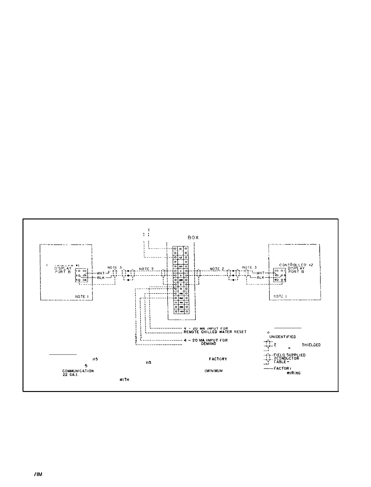
WIRING
The contractor will mount the LLLB control panel within sight
of the chillers in a reasonably accessible location. A source
of 115 volt AC control power must be connected to terminals
L1
and L2 inside the LLLB box. Wiring must be sized to carry
not less than 5 amps. Shielded twisted pair wiring of 22 AWG
minimum should be connected between the remote controller
and communications port B of the Display
EnGinn
on each
MIcroTech
panel.
See the appropriate field connection wiring diagram for
specific details.
On dual compressor PFH units, the panel may be factory
mounted and the wiring complete.
REMOTE RESET CONTROL
In the event remote reset of chilled water and/or electrical de-
mand will be provided, the customer furnished 4 to 20
mA
transmitter(s) and wiring must be connected to the LLLB box,
and not to individual
MicroTech
unit panels. The “Set-up Op-
tions” key for each
MicroTech
panel must, however, reflect the
holiday shut-off dates are wanted, set the holiday month and
reset opt-ions(s) chosen.
Figure
10. Lead-Lag
Wiring
Diagram.
NOTE
I
:
I
LEAD/LAG
00X
r--------l
----_
___
_____-_--
1
I
I
I
CONTROLLER
.I
LEGEND
IDENTIFIED TERMINAL
;
1
:
L____--______-_____
4
_
20
MA
,NPUT
FOR
t____________________
REMOTE
DEM4ND
LIMIT
NOTES:
I.
ON PFH UNITS.
115
VOLT POWER WIRING AND COMMUNICATION WIRING IS FAClORY
INSTALLED. ON FIELD INSTALLED UNITS. II5 VOLT AC POWER MUST BE PROVIDED
(MAXIMUM 5 AMPS).
2.
;;~~,~,lC4TION
CABLE MUST BE TWISTED PAIR OR SHIELDED CABLE
iMINIMUM
3. ADAPTER CABLE PROVIDED
llTn
FIELD MOUNTED LEAD/LAG BOX.
. UNIDENTIFIED TERMINAL
-,=+
FACTORY SUPPLIED
Gt
CONDUCTOR
SHIELGED
._:
CABLE
-
22 GA. MIN.
-+-b-FIELD
SU?PLIED
_:_;_Z
CONDbCTOR
SHIELDED
1
CAELE
-
22 GA. MIN.
._
-FACTOR.r
WIRING
-----FIELD
WIRiNG
Page 10
I
IM
403