OIL GAUGE TRANSDUCER (OGT)
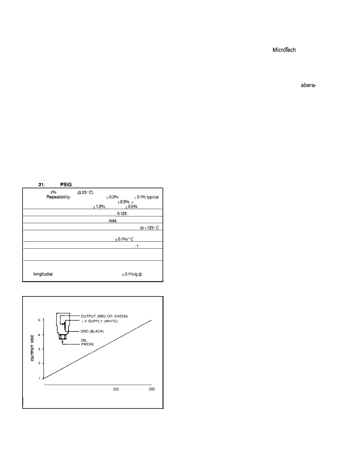
The oil gauge transducer is a zero to 300 PSI input, 1 to 5
volt DC output LVDT type transducer. The device is powered
by a 17 VDC unregulated power supply from the daughter
board and produces a linear 1 to 5 volt DC as output as the
pressure is increased from zero to 300 volts.
The transducer senses gross oil pressure (saturated suc-
tion plus oil pressure). Actual, or net oil pressure is the gross
oil pressure minus the saturated refrigerant suction pressure
as calculated from the refrigerant saturated suction
temperature.
At 150 PSI gross oil pressure, the transducer should deliver
+3 VDC to the TS4 terminal number 11 on the daughter
board.
If the DC voltage varies appreciably from the linear curve
as depicted in Figure 21, the transducer may be bad and re-
quire replacement.
If the DC voltage equals 4.9 to 5.0 volts, the unit will shut-
down, and the display will read “Off: Oil Gauge Sensor”.
Since the DC voltage output from the transducer is a func-
tion of oil pressure into the device, check the oil pressure with
service gauges before condemning the transducer.
Bear in mind also that during pre-lube, with a high stand-
by refrigerant pressure, gross oil pressure will be much higher
than may normally be expected with the chiller running.
If pressures permit, adjust the oil pressure relief valve to
lower actual oil pressure, and the resultant DC voltage signal.
Table
21: O-300
PSIG
ACCURACY
(%
Full Scale
@
25C)
l
Repeatibility:
~0.3%
max.,
+O.i%
typtcal
l Linearity:.
*
0.3%,
*
0.3% typical
l
Hysteresis:.
*i.O%
max., iO.5% typical
MAXIMUM POWER RATING:.
.0.125
watts
RESPONSE TIME:. .less than 15 milliseconds
OPERATING TEMP. RANGE:
-40
l0+125”C
TEMPERATURE SENSITIVITY OVER ABOVE OPERATING
RANGE:.
_tO.l%/“C maximum
TOTAL RESISTANCE:.
.l
K-ohms
OUTPUT SIGNAL AMPLITUDE:. spans available to 60% of supply
voltage
ACCELERATION EFFECTS
l Acceleration-induced error under worst case conditions (In
longitudial
axis with gas medium):.
*0.1%/g
@
60 Hz
l Contact lift under conditions defined above:. none detectable
Figure
28.
Oil Gauge Transducer
WIRING
0
100 200
300
PSI (INPUT)
I
SENSORS
With the exception of sensors numbered 11, 12, and 13 the
omission or the failure of analog sensors connected to the
daughter board terminals TS3 and TS4 will be discerned by
the microprocessor as a fault. The unit will shut down and
the faulty sensor will be identified in the
MicroTech
display.
This presumes that the fault exceeds pre-programmed limits
in the software. For example, if any of the eleven (11)
temperature sensors short, or open, their electrical resistance
will instantly trigger a service shutdown.
If on the other hand, one of the sensors becomes erratic,
or erroneous in reflection of a temperature value, this
abera-
tion will only be apparent following analysis of the chiller’s
operating data. In the event a temperature sensor is suspect,
the electrical resistance at known temperatures may be check-
ed in comparison to the “Resistance vs. Temperature” table
included.
Sensors 11, 12, and 13 also will produce an equipment shut-
down and identifying display if these sensors fail. Unlike the
thermistors, however, each of these decay to zero when the
chiller is off; and sensor number 11 (the Reset signal) may
remain at zero while the chiller is running without trigging a
fault indication.
Sensors numbered 12 and 13 must signal more than zero
while the unit is running, and less than a pre-determined max-
imum to prevent a fault statement and a trip.
Page
36
/
IM
403