STARTING THE UNIT
INITIAL START-UP CHECKS
The following checks of the control system are recommend-
ed before power is applied to the compressor.
1.
Check that flow switches, interlocks, or jumpers (if required)
are properly connected to
MicroTech
terminals 6 to 22, 10
to 61, 10 to 63, 11 to 12, and 58 to 66.
Closure of these contacts during or prior to the start-up
sequence is required to complete steps in the logic control
path.
SEE
CAUTION
STRIP TESTING
D
on
page
6.
Proof’of closure of these contacts and others required
to be closed is given by the glow of appropriate
LEDs
on
the daughter board. (See Table 8).
2. If a remote start-stop control (SW2) will be used, the con-
trol option must be activated in the logic panel (see Table
17) and wiring must be connected across terminals 9 to 64.
Conversely, if the logic control panel has been set to call for
the remote start-stop option, then a connection must be made
across terminals 9 to 64. If remote start-stop is not intended,
then the programmable software must be left on “Local”. Use
the service or operator password, if required.
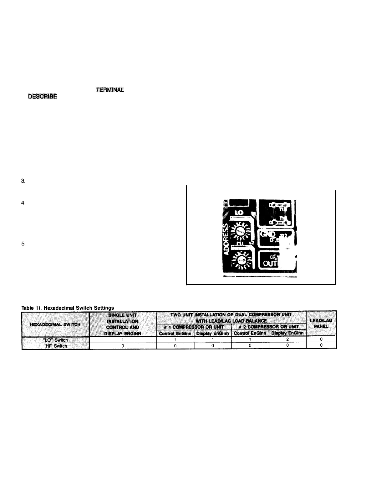
Check that hexadecimal switches (see Figure 17) on the
mother board and on the display EnGinn are properly set.
Correct settings are shown in Table 11.
Check that the LED on the power cartridge and the LED
on the display EnGinn are blinking.
If one is blinking and one is out, or if one or both are lit
continuously, or if both are out when they should be blink-
ing, the condition indicates a fault which must be in-
vestigated. See the Trouble Analysis section.
Energize the control panel without the compressor oper-
ating, and check or set all desired options and required
setpoints.
HEXADECIMAL SWITCHES (Address switches)
MicroTech
control panels do not include any DIP switches to
set. They do include hexadecimal switches (sometimes call-
ed simply hex switches). These switches identify the com-
munications address by which one microprocessor provides
and/or retrieves information to or from another.
There are two hex switches on the Control EnGinn and two
on the door-mounted Display EnGinn. When a Lead-Lag/Load
Balance panel is supplied, either with a dual compessor chiller
or with two single compressor chillers, there are two more
hex switches mounted on the Mother Board in this panel.
These switches are approximately
1/2"
square, with an ar-
row shaped screwdriver slot in the center face. Around the
perimeter of the adjusting screw, the face of the square block
contains the numbers 0 thru 9 and the letters A through F.
Next to or above each switch, on the mounting panel, let-
tering will identify the switch as “Hi” or “Lo”. Do not assume
the ‘high’ or ‘low’ from their physical position.
Switches should be factory set. If there are two units being
connected through a lead/lag
MicroTech
panel, the switch set-
tings may not be correct. In any case verify that the arrow
in each hex switch points to the number listed in the table.
IMPORTANT! If it is necessary to change the hex switch
settings, in order to input those new settings into the micro-
processor memory, the panel must be powered down, then
re-energized. This can most readily be accomplished by trip-
ping, than resetting the 3 amp control panel circuit breaker.
Fiaure 17. Hexadecimal Switches
*
Arbitrarily select one of the units to be “Number 2”.
IMPORTANT! If it is necessary to change the hex
switch
settings, in order to input those new settings into the microprocessor memory, the panel must be powered
down, then re-energized. This can most readily be accomplished by tripping than resetting the 3 amp control panel circuit breaker.
Page 18 I IM
403