If this action is not desirable because the controlled pump
is the principal system pump, the alarm relay circuit may be
used with a normally closed contact to provide a parallel con-
tact in the pump’s control circuit.
Should this latter wiring be considered provision must be
made to open this circuit during scheduled downtimes.
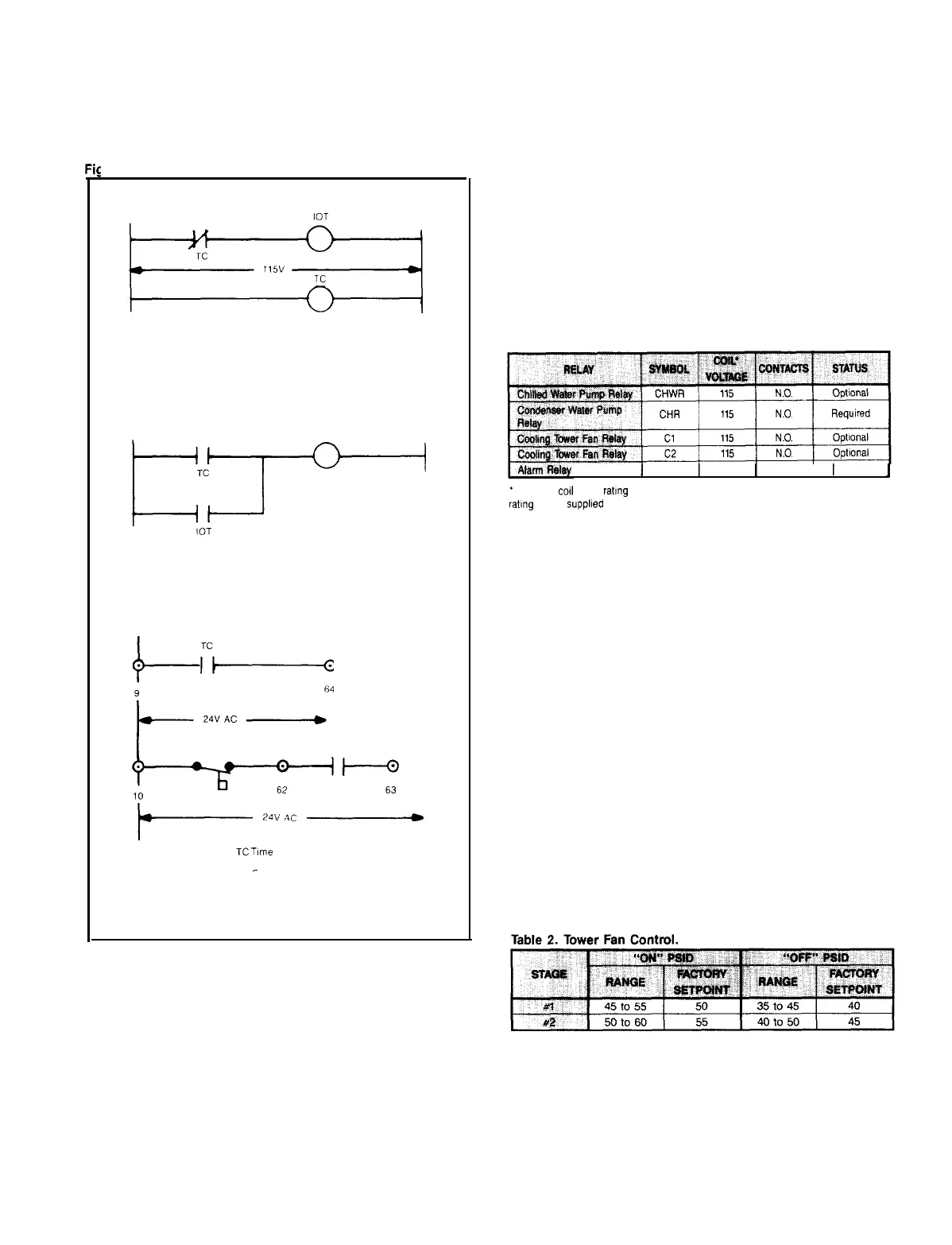
lure 9. Wiring Schematics.
PC
ccr’”
REMOTE SWITCH
TC
I I
0
9
64
L
24V AC
h
.
t--
‘iL_
24:.21C
i.
TC
.llrne
Clock
PC
-
Pump Control
IOT Instant ON Timer
(3
to
4
sec
)
ALARM RELAY
(See Table
1
for Relay Coil Characteristics)
Provision exists on the
MicroTech
control panel to activate an
alarm circuit whenever a fault occurs.
The 24 volt alarm relay (field supplied) is normally energized
whenever 120 volt control power is applied to control panel
terminals number Ll and L2 and the 3 amp circuit breaker
is closed.
If a fault occurs, preventing the chiller from operating, and
the fault is recorded by the
MicroTech
control, the alarm relay
circuit will open, de-energizing the relay.
Normally closed relay contacts should be used in a separate
circuit to annunciate the fault.
NOTE: If an alarm relay is used, we suggest that the annun-
ciation circuit include a service ‘interruption’ switch to pre-
vent unnecessarily triggering an alarm during normal service
operations.
Table 1. Customer Furnished A.C. Operating Relays.
A
24
1
N.C.
1
Optional
1
*
No single
co11
with a rating of more than 25 VA may be connected. Maximum total VA
rating of field supplied coils shall not exceed 125 VA.
COOLING TOWER FAN CONTROL
The
MicroTech
panel includes software capability to start and
stop two stages of cooling tower fans in response to differen-
tial refrigerant pressure.
The system offered provides a form of head pressure con-
trol. If it will be used, the installer must provide one or two
115 volt coil relays to be wired as shown in the field wiring
diagram. See Table 1 for relay characteristics.
The field supplied relay(s) will be energized as required by
the operating compressor’s refrigerant pressure differential
through the factory mounted solid-state relays. These latter
relays will energize and de-energize based upon the settings
programmed for them under the set-up options keypad.
Contacts from the installer furnished relays will be impos-
ed in the starting circuit for the tower fan(s) contactor coil.
The
MicroTech
design is such that one or both of the tower
fan control relays may be omitted, and tower fan control fur-
nished in another manner.
The installer should also note that tower fan cycling by itself
may not be adequate to prevent lower than desirable refrig-
erant condensing pressure. If the building load, tower and fan
size or arrangement, and ambient wet bulb temperature com-
bine to require adjustments in water flow in the condenser
water system, the engineer or installer should provide that
piping and control.
IM 403
/
Page 9