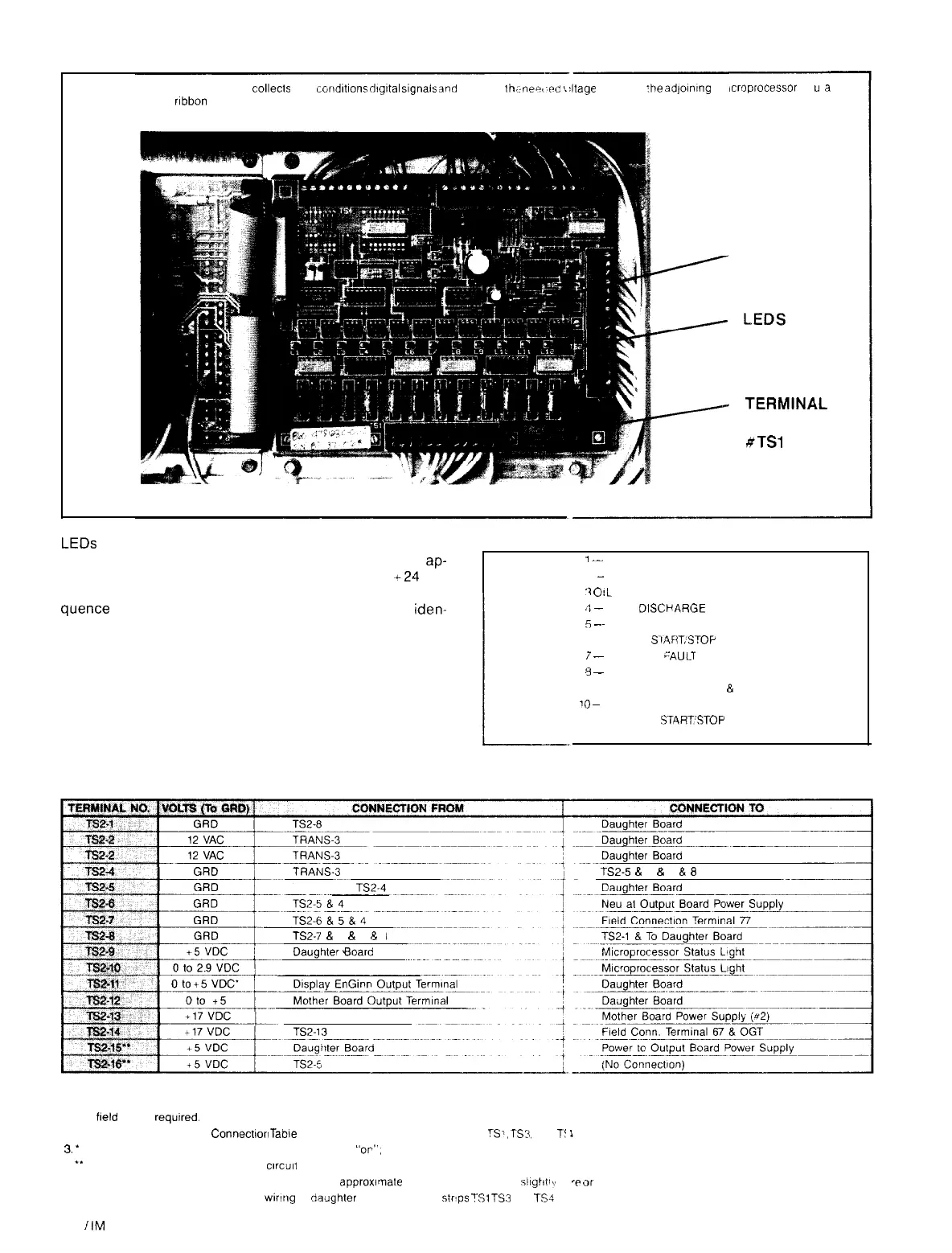
Figure 15. Daughter Board
NOTE: The daughter board
colle&
and
condltlons
dIgItal
signals
and
delivers
lh,:
neww
L
Jtage
levels to
:he
adjoinIng
m
plug-in
ribbon
cable
vzroprocessor
thr
FUSE
TERMINA
STRIP
#TSl
ua
rL
LEDs
located on the daughter board are identified as Ll, L2,
L3, etc. These lights will glow when the contact in the
ap-
propriate protective circuit is closed. Contacts are +24 volt
AC and must be closed, lighting the LED for the starting se-
quence to be completed. LED numbered circuits are
iden-
tified in Table 8.
Table 8. LED Description
1
--
SURGEGUARD
2
-
MOTOR TEMPERATURE
‘1
O!L
DIFFERENTIAL SWITCH
?
-
HIGH DISCt’ARGE PRESSURE
5
-~
EVAPORATOR LOW PRESSURE
6 --- PANEL SIARTSTOP
i
-
STARTER
cAUL.T
Y
-
CONDENSER FLOW & PUMP
9 -- EVAPORATOR FLOW
&
PUMP
10
~ STARTER TRANSITION
11 -- REMOTE
START’STOP
12 -- VANE CLOSE SWITCH
Table 9. Daughter Board Terminal Connections.
TS2-5
&
6
&
7
8
8
TRANS.2 &
TS2-4
TS2-7
& 6
Ei
5
8
4
Daughter Board
Daughter Board
NOTES:
1. No
field
wiring
required.
2. See Sensor and Control
Connectlorl
Taole
for connections to terminal boards
TSi,
TS:!,
and
T!
1
3.
’
Pulsed volts to power status LED’s Zero volts LED
“or”.
5 volts LED “off”
4
**
Under control of the “Watchdog”
cwcult
5. 12 volt AC and unregulated 17 VDC voltages are
approwmate
Actual values may be
s/lghtlv
m
‘?
tir
less
6 See the Control Devices Table for
wiring
to daiighter board terminal
strtps
TSl
TS3
arc
1%
Page 16
I
IM 403