VACUUM FLUORESCENT DISPLAY
The display type used was carefully selected for its clarity and
The other four (4) reset options require an external 4 to 20
long life. The system is equipped however to automatically
mA
signal, input to the field connection terminals 69, 70, and
shut off the display if keypads have not been pressed within
71. The 4 to 20 milliamp transmitter will itself be controlled
the preceeding ten minutes.
by a demand limiter for motor current limit, or for chilled water
elevation based upon an EMS control.
RESET CONTROL OPTIONS
The
MicroTech
panel is programmed to accept:
No Reset.. .Reset
;
None
Entering Chilled Water. Reset = ENT
Leaving Chilled Water. Reset =
ChW
Electrical Demand. .Reset
=
AMP
Electrical Demand
&
ENT. Reset = AMP ENT
Electrical Demand
&
ChW.
Reset = AMP CHW
If the Installation consists of multiple chillers, or a single
dual compressor chiller, with a lead-lag/load balance (LLLB)
control, the remote reset transmitters are connected to the
lead-lag control panel, not to the individual
MicroTech
panels.
The control signal is then sent to the individual chiller through
the LLLB. See the field connection wiring diagram for the
LLLB accessory panel.
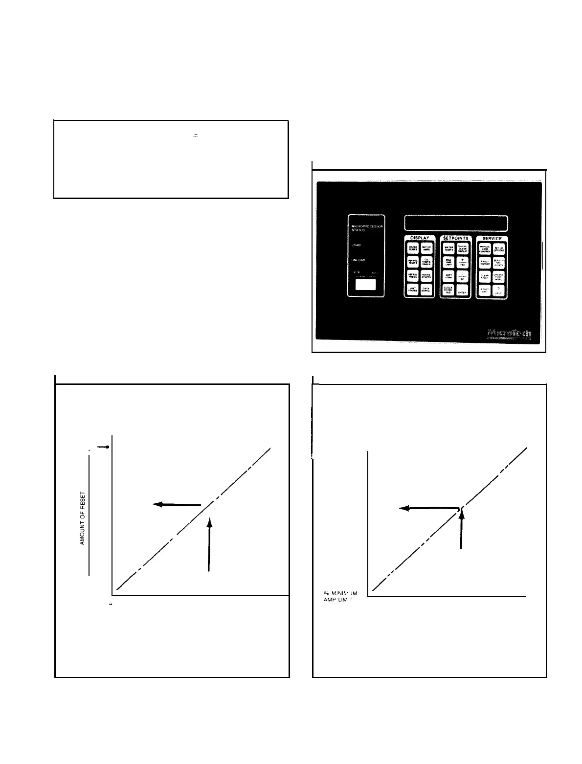
Figure 3. Keypad and Display.
If entering chilled water is elected as a reset option, no ad-
ditional control is required. The
MicroTech
panel will attempt
to control a fixed return water temperature. To do so, as the
building load is reduced, return water temperature will
decrease. The microprocessor, however, wilt check return
water temperature every 2 to 60 minutes (operator adjustable)
and elevate the leaving chilled water temperature to regain
the original return water (entering water) temperature.
Since the “Start” and “Stop” temperatures are temperature
differences from the leaving chilled water
setpoint
temperature, the actual “start” and “stop” temperatures also
reset as the leaving chilled water temperature is reset.
As building load is increased, the return water temperature
would increase, causing the microprocessor to lower leaving
chilled temperature, thereby returning the return chilled water
temperature to its original value.
Figure
4. Max. Chilled Water Reset
MAXIMUM
CHILLED WATER
RESET
ZERC
RESET-
- ADJUSTABLE UP TO
15
F MAX
/
ACTUAL
mA
INPUT
CAI.CULATES THE
AMOUNT OF RESET
BASED ON MAXIMUM
DESIRED AT 20 mA
i
mA-DC
REMOTE
RESET
INPUT
SIGNAL
20
Fi
I
gure 5. Percent Max. Amp Limit.
%
MAXIMUM
AMP
L
IMIT
%
REMC E
AMP
LIMIT
/
I
/
+
,/
I
,
/
‘I
/”
4
mA-DC
20
REMOTE RESET
INPUT
SIGNAL
IM
403 I Page 5