IM-738 Page 41
Intake Hood Damper (0 to 100% outside air)
Units requiring 100% outside air are provided with a rain hood
and dampers which may be controlled by a single actuator. The
actuator provides two-position control for opening the
dampers fully during unit operation and closing the dampers
during the off cycle. No unit mounted exhaust dampers are
provided.
Intake Hood Damper (0 to 30% outside air)
These dampers are intended to remain at a fixed position dur-
ing unit operation, providing fresh air quantities from 0 to 30%
of the total system airflow, depending on the damper setting.
This setting is made at the linkage rod on units with manually
adjustable linkages.
On units provided with MicroTech II controls, the damper
position may be set at the controller keypad. During unit oper-
ation, the two-position actuator drives the damper to the posi-
tion set on the keypad. During the off cycle, the damper is
automatically closed.
No unit mounted exhaust dampers are provided with this option.
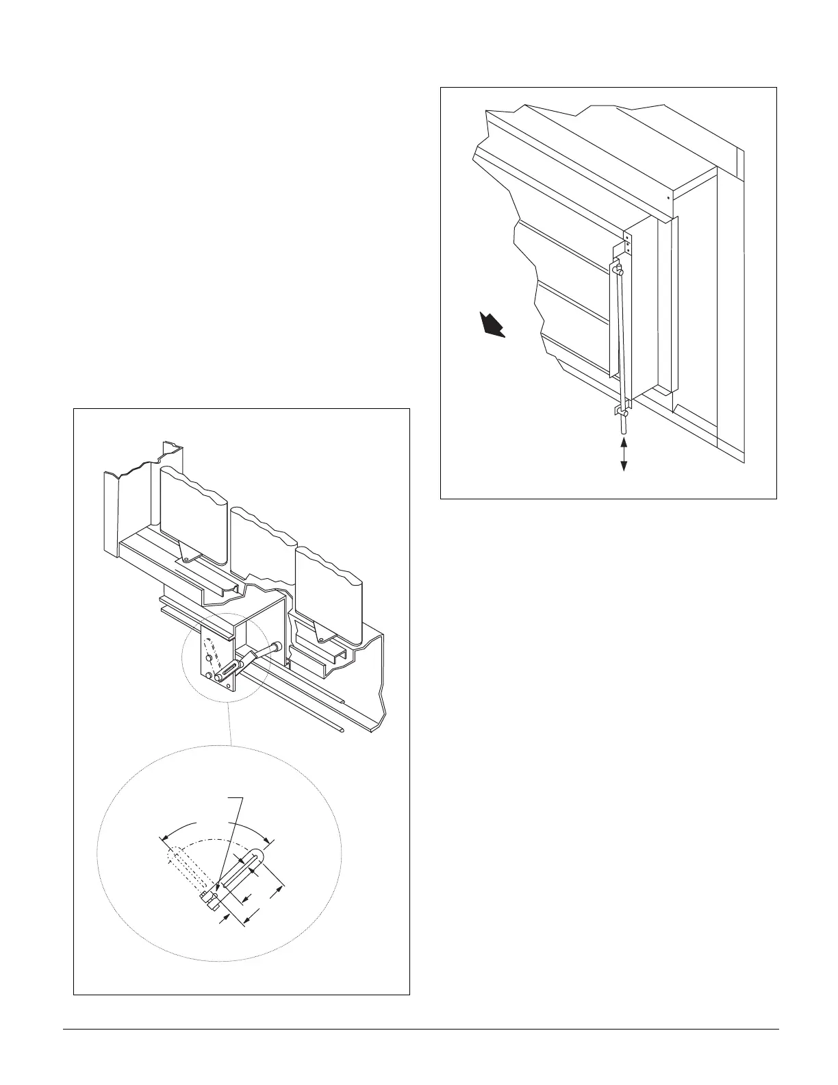
Figure 47. Intake Hood Damper Adjustment.
Figure 48. Damper Linkage Bar Typical for all sizes.
Size 15C-40C shown.
Cabinet Weatherproofing
This unit ships from the factory with fully gasketed access
doors and cabinet caulking to provide weatherproof operation.
After the unit has been set in place, all door gaskets should be
inspected for shipping damage and replaced if necessary.
It is recommended the unit be protected from overhead runoff
from overhangs or other such structures.
Field assembled options such as external piping or vestibules
are to be recaulked per the installation instructions provided
with the option.
Installing Ductwork
On bottom-supply/bottom-return units, the installing contrac-
tor should make an airtight connection by attaching field fabri-
cated duct collars to the bottom surface of either the roof curb's
duct flange or the unit's duct opening if a McQuay roof curb is
not used. Do not support the total weight of the ductwork from
the unit or these duct flanges. Refer to Figure 49.
Units with optional back return, side discharge, or end discharge
(on RFS units) all have duct collars provided. The discharge
duct collars on a side discharge unit are exposed by removing
the plenum section access door and the door gasketing.
Flexible connections should be used between the unit and
ductwork to avoid transmission of vibration from the unit to
the structure.
Ductwork should be designed per ASHRAE and SMACNA
recommendations to minimize losses and sound transmission.
O A
C l o s e d
O A
O p e n
3 . 0 0
. 2 5
. 7 5
9 0 °
S t r o k e
S h a f t . 5 0 0 D i a .
x 1 . 5 0 L o n g
A i r f l o w
3 . 1 5 " ( 8 0 m m )
M a x . S t r o k e o f
D a m p e r L i n k a g e B a r