IM-738 Page 7
Refrigeration Piping
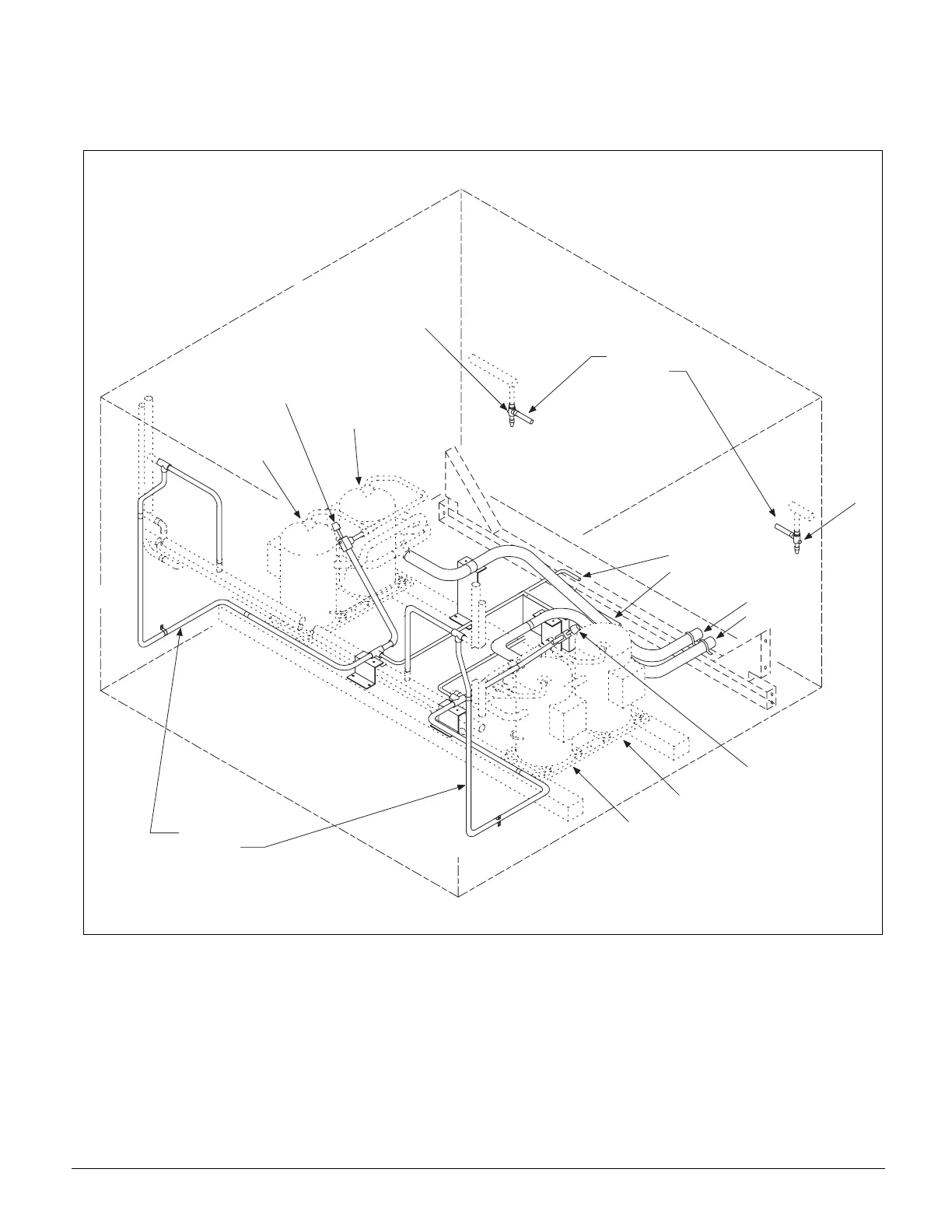
This section presents the unit refrigeration piping diagrams for
the various available configurations. Component numbering
conventions are also shown. Refer to Figure 4, Figure 5 on
page 8 and Figure 6 on page 9.
Figure 4. Condenser Piping 4 Compressors/2 Circuits (045C - 060C) — 3 Compressors/2 Circuits (070 - 075C)
C o m p r e s s o r # 1
C o m p r e s s o r # 3
C o m p r e s s o r # 2
C o m p r e s s o r # 4
1
2
3
4
D i s c h a r g e L i n e s
C i r c u i t # 1
C i r c u i t # 2
L i q u i d L i n e s
C i r c u i t # 1
C i r c u i t # 2
O p t i o n a l
H o t G a s
B y p a s s
L i n e s
C i r c u i t # 1
C i r c u i t # 2
S u c t i o n
L i n e s
C i r c u i t # 1
C i r c u i t # 2
Legend
1 - Discharge Shut-off Valve - Circuit #1
2 - Liquid Shut-off Valve - Circuit #1
3 - Liquid Shut-off Valve - Circuit #2
4 - Discharge Shut-off Valve - Circuit #2