5
4 - Functions of the components
There are four basic systems that make up the heater: the fuel system, the ventilation system, the ignition
system and the flame control system.
Fuel system: The pump takes fuel from the tank and pressurises it. It pushes it through the filter and
the pump to make it exit as a very fine mist from the nozzle in the combustion head.
Ventilation system: The motor turns the fan. It pushes air into the combustion chamber. The air
entering the combustion chamber mixes with the atomised fuel for combustion. The flame that is
created, lightly touches the internal wall of the combustion chamber. This chamber reaches a
temperature that is so high that the front baffle becomes incandescent, heating anything in front of it
by radiation.
Flame control system and Ignition system: The transformer sends voltage to the electrodes that
ignite the mixture of air and fuel, the flame control shuts off the machine if the flame is interrupted.
Upon subsequent ignition, the equipment must be reset manually.
Electrical system: This system allows heater operation, in all of its parts, as soon as it is connected
to suitable mains voltage that conforms to that shown on the heater's identification plate.
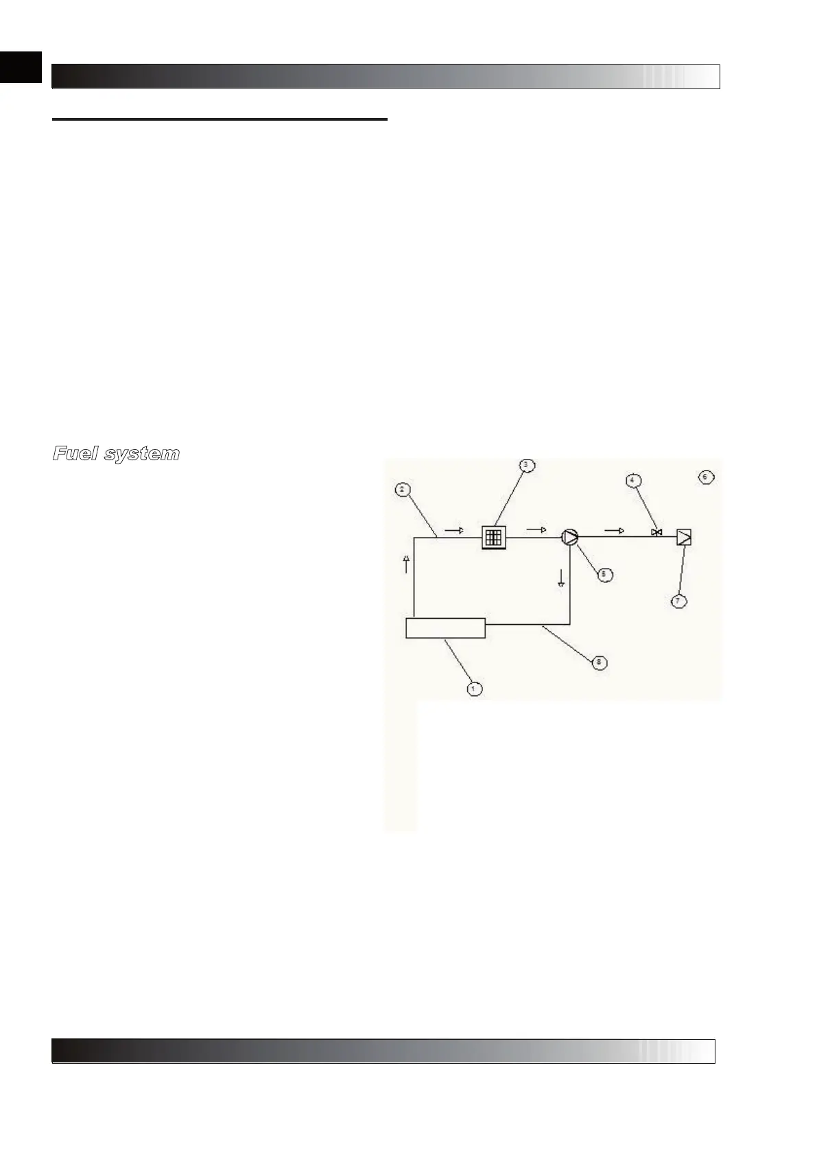
Fuel system
As shown in the fuel system diagram below, the fuel
is taken in by the pump in the burner. The fuel
passes from a rigid pipe and continues up to the line
filter. Here the fuel is filtered by a cartridge,
pressurised and sent at suitable pressure to the
nozzle. At the nozzle, the fuel is filtered a third time
before being suitably atomised.
2-Suction pipe
3-Fuel filter
4-Solenoid valve
5-Fuel pump
6-Discharge pipe
7-Nozzle
8-Return pipe
en
it
de
es
fr
nl
pt
da
no
sv
pl
ru
cs
hu
sl
tr
hr
lt
lv
et
ro
sk
bg
uk
bs
el
zh