30750 14MBX
M1 63
14.3.2 Adjusting the ∆ P of the cross-over valve
Right side:
1- Place the machine equipment in a blocked position
and turn the direction to the right, engine in maximum
regime.
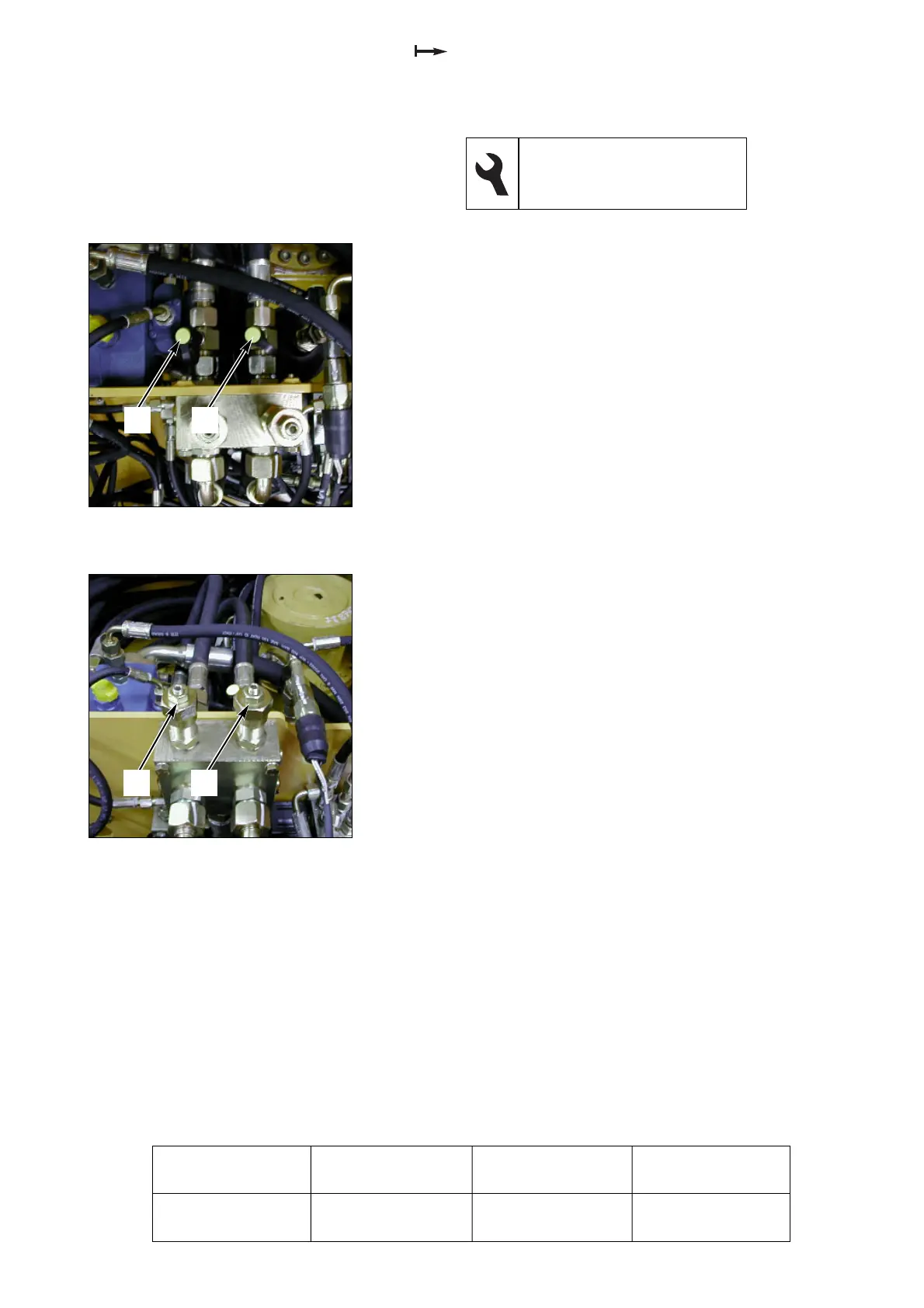
2- Measure the difference in pressure between (1 fig. 1)
and (2 fig. 1) using the two manometers.
3- Loosen the lock nut and turn the screw (1 fig. 2) of the
cross-over valve clockwise in order to increase the ∆ P
of the right side.
Left side:
4- Place the machine equipment in a blocked position
and turn the direction to the left, engine in maximum
regime.
5- Measure the difference in pressure between (1 fig. 1)
and (2 fig. 1) using the two manometers.
6- Loosen the lock nut and turn the screw (2 fig. 2) of the
cross-over valve clockwise in order to increase the ∆ P
of the left side.
17 flat spanner
5 flat hexagonal spanner
2 manometers, 0-600 bars
Operation
Pressure
(bars)
Measurement
(ref. no.)
Adjustment
(ref. no.)
∆ P direction
225 (+ 5 - 5)
1 fig. 1 and 2 fig. 1
1 fig. 1 and 2 fig. 1
1 fig. 2
2 fig. 2
Fig. 1 Cross-over unit
Fig. 2 Cross-over unit
1
2
1
2
 Loading...