14MBX 30750
62 M1
14.3 Direction adjustment procedure
14.3.1 Adjusting the primary controller
Take great care when removing the flex, as it
may be under pressure.
Place the equipment on the ground, stop the
engine, make the contact and cancel any
residual pressure by activating the keys in all
directions.
1- Block the direction by using the mechanical locking
device located inside the cabin.
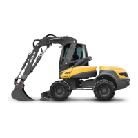
2- Remove and stop up the flex (1 fig. 1) on the cross-
over unit.
3- Point the tower to the right (in order to put the flex
under pressure), engine in maximum regime.
4- Measure the pressure (2 fig. 1) using the manometer.
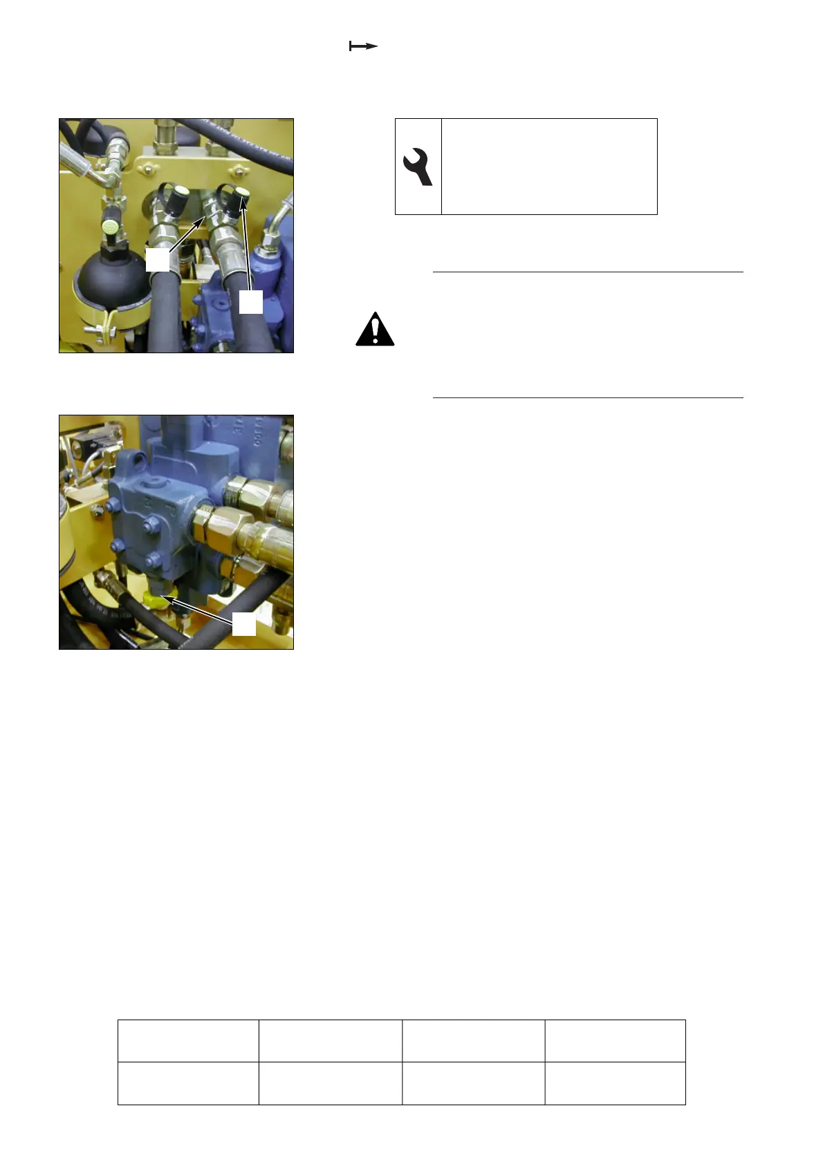
5- Loosen the lock nut and turn the pressure controller
screw (1 fig. 2) clockwise to increase the pressure.
6- Reconnect the flex and move on to adjusting the ∆ P
of the cross-over valve.
Operation
Pressure
(bars)
Measurement
(ref. no.)
Adjustment
(ref. no.)
Primary controller 250 (+ 5 - 0) 2 fig. 1 1 fig. 2
17, 27 and 30 flat spanners
5 male hexagonal spanner
G DS16 1/2” female stopper
G DS16 1/2” male stopper
Manometer, 0-600 bars
Fig. 1 Cross-over unit
Fig. 2 SX18 valve block
1
2
1
 Loading...