14MBX 30750
70 M1
Fig. 3 Equipment pump
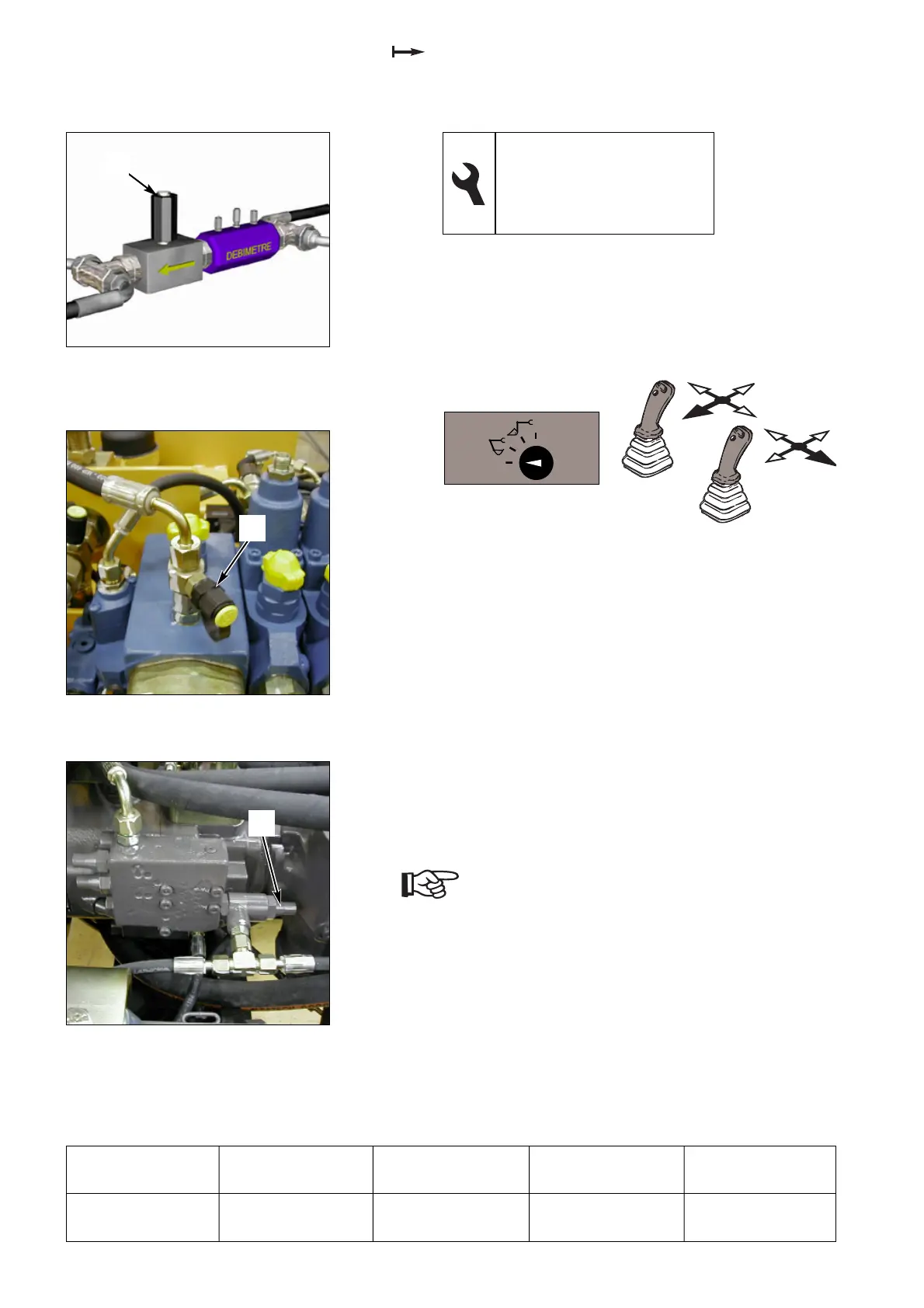
Fig. 2 SX18 valve block
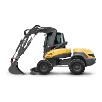
Fig. 1 Flow meter adaptation kit
(TOP-TEST/MX)
1
14.4.6 Adjusting the power regulation
1- Set the selector switch to “MECALAC 1”, pull the left
key towards the back, push the right key to the right
(blocked position) to allow the oil to circulate (small
chambers of the dipper ram and bucket ram).
2- Accelerate the engine to maximum regime.
3- Reduce the flow (140 l/min) using the tap on the flow
meter (1 fig. 1).
4- Measure the pressure (1 fig. 2) using the manometer.
5- Loosen the lock nut and turn the pressure controller
screw (1 fig. 3) clockwise to increase the pressure.
6- Check that the regime of the engine does not exceed
2,000 rpm.
Note: For the air-conditioning type machines,
power regulation of equipment pump.
Q = 140 l/mn for 235 bars (+ 10 - 0).
All other values remain unchanged.
13 flat spanner
4 male hexagonal spanner
Inductive sensor
Manometer, 0-600 bars
Flow meter adaptation kit
Operation
Pressure
(bars)
Speed
(rpm)
Measurement
(ref. no.)
Adjustment
(ref. no.)
Power regulation
at 140 l/mn
245 (+ 10 - 10) > 2,000 1 fig. 2 1 fig. 3
 Loading...