Genio 350 EVK
Genio 350 Evaluation Kit Hardware User Guide
Unclassified
MediaTek Proprietary and
Confidential
© 2022 MediaTek Inc. All rights reserved.
Unauthorized reproduction or disclosure of this document, in whole or in
part, is strictly prohibited.
Page 22 of
4.3 How to Configure the MIPI CSI Path
Location
Note
J401 Select signal path
J402 Select signal path
J403 MCLK switch
J404 RST switch
J502 AP1302 test mode
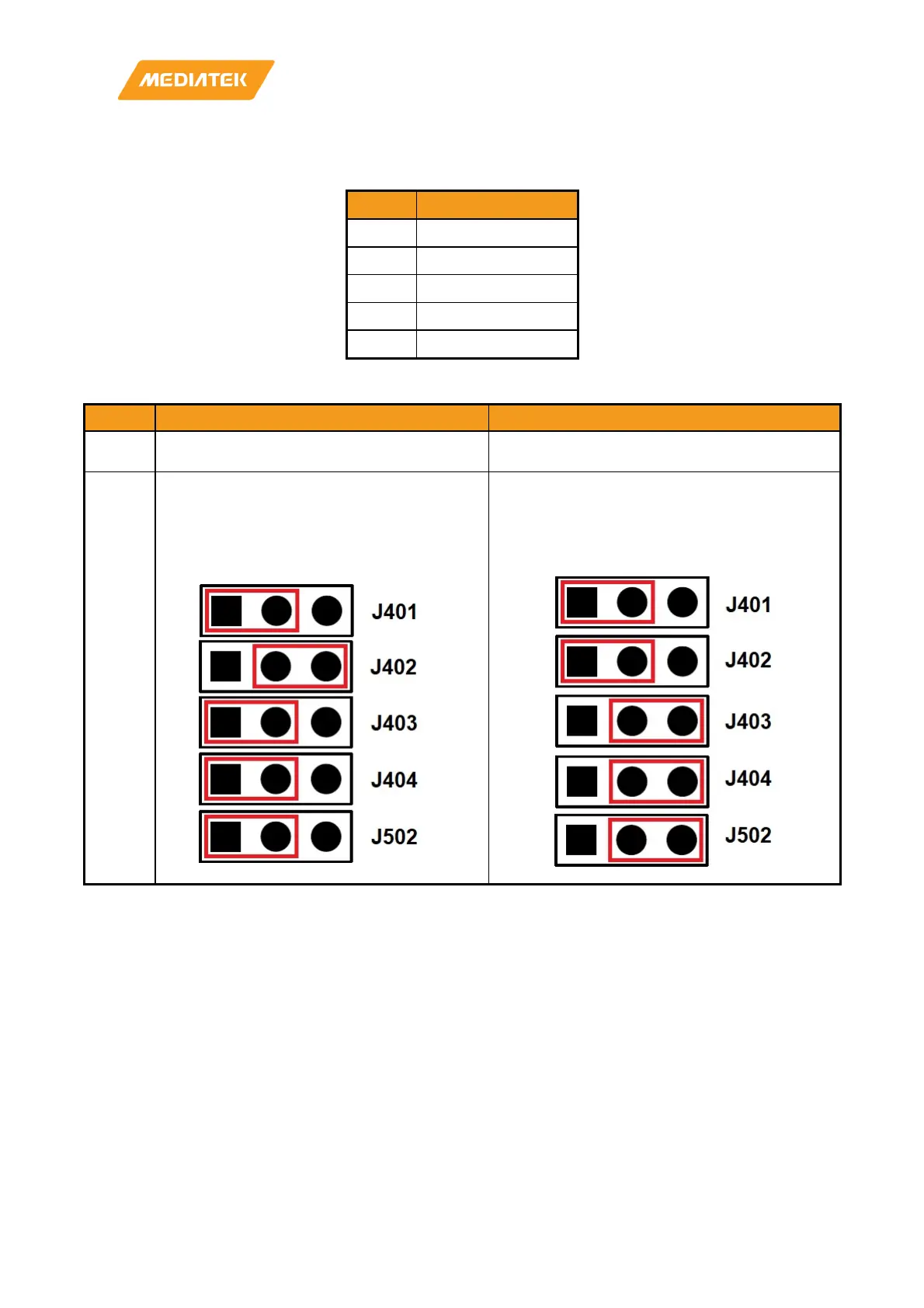
Table 4-2 Jumper Selection for CAM or CAM+ISP
Setting
Direct to Main Board (CAM Only)
Through ISP (CAM + ISP)
Camera
Module
Put camera module on CON601 Put camera module on CON602
Jumper
1. Put a shunt to short J401 pin 1 and pin 2.
2. Put a shunt to short J402 pin 2 and pin 3.
3. Put a shunt to short J403 pin 1 and pin 2.
4. Put a shunt to short J404 pin 1 and pin 2.
5. Put a shunt to short J502 pin 1 and pin 2
1. Put a shunt to short J402 pin 1 and pin 2.
2. Put a shunt to short J402 pin 1 and pin 2.
3. Put a shunt to short J403 pin 2 and pin 3.
4. Put a shunt to short J404 pin 2 and pin 3.
5. Put a shunt to short J502 pin 2 and pin 3.
Table 4-1 Block Diagram of Camera Sub-Board