Genio 350 EVK
Genio 350 Evaluation Kit Hardware User Guide
Unclassified
MediaTek Proprietary and
Confidential
© 2022 MediaTek Inc. All rights reserved.
Unauthorized reproduction or disclosure of this document, in whole or in
part, is strictly prohibited.
Page 12 of
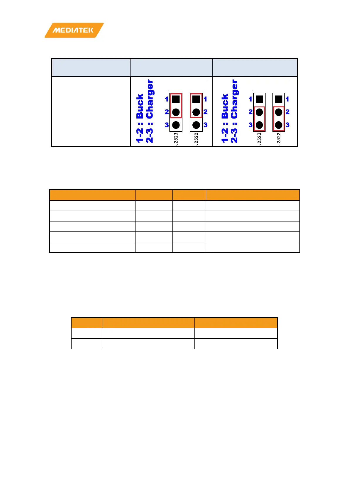
Current Rating System Power from Buck
System Power from
Charger
4 Ampere
Figure 3-2 Jumper Selection for System Power
3.3 I/O Interface
LED Indicators
There are three LED indicators.
LED Indicators Location Color Note
System Power Indicator D1206 Green
Reset Indicator D1207 Green LED is off if reset signal is low.
System Power Indicator D1001 Green LED is on if system is on.
Charging Status Indicator D1 Red LED is on while charging.
System Power Indicator D1206 Green
Figure 3-3 Jumper Selection for System Power
UART
There are two UART (UART0 and UART1) consoles with USB to UART Bridge ICs on Genio 350-EVK. Users can
use these consoles for debug purpose. The connectors are Micro USB type.
• Supports word Lengths from 5 to 8 bits with an optional parity bit and 1 or 2 stop bits
• Supports baud rates from 110 bps up to 961,200 bps
• FTDI USB to UART Bridge FT232RL
UART0 CON461 (Micro USB) Core Processor Log
UART1 CON462 (Micro USB) DSP Log
UART0 CON461 (Micro USB) Core Processor Log
Table 3-4 UART Ports
I2C
• Four I2C buses (I2C0 to I2C3)
• Supports Master Mode Only
• Adjustable clock speed for LS/FS/FS+ mode operation
• Supports 7-bit address
 Loading...