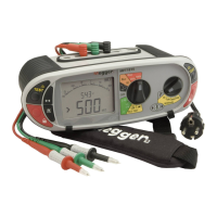
, on the instrument.
Release the test button after the displayed reading has settled. Circuit will now discharge safely.
Note: A 1000 V warning is displayed whenever the 1000 V range is selected for the first time and the TEST button is pressed.
6.2 Insulation test lock
To lock an insulation test ON, hold down either of the TEST buttons followed by either of the RED LOCK buttons.
To release the “Locked on” insulation test, press the TEST button.
Warning: The test voltage will be permanently present on the test probes or crocodile clips when in the locked position.
Warning: Auto discharge - Auto discharge facility automatically and safely discharges the circuit at the completion of an
insulation test.
Live circuit warning - operates when connected to Live circuits > 25 V. Testing is still permitted.
Test inhibited - Live circuits greater than 50 V will inhibit testing.
6.3 Measurement methods and sources of error
Method of measurement
The selected dc test voltage (current limited to less than 2 mA d.c).is applied to the circuit under test and the resistance is
calculated from measurements of the resulting voltage and current.
Capacitive circuits can take some time to charge. This is displayed as an increasing voltage that takes longer to reach its
maximum than normal.
The reading is stable with a circuit capacitance less than 5 µF.
7. Loop impedance testing
IMPORTANT
This measurement requires both selector knobs to be set to the Loop testing mode (GREEN RANGES) on the MFT1720 and 1730 or just
the left knob on the 1710.
This is a live circuit test. All precautions relevant to working on live circuits, to ensure the safety of the operator and any
other personnel should be in place.
Overview of the LOOP IMPEDANCE test
A Loop impedance test is the measurement of the impedance of a circuit whilst the circuit is electrically live.
Unlike a continuity test, a loop impedance test applies a load to the circuit and measures the change in the circuit voltage, from which
the loop “resistance” is calculated.
For those circuits protected by an RCD the load that is connected Phase to Earth must be small enough not to trip the RCD.
Consequently there must be many tests performed to establish the loop impedance of the circuit. These are automatically performed
and the end result is displayed.
Test Lead Null:
The MFT does not need the resistance of the test leads to be nulled for this test. They are already calibrated into the measurement
circuit at 0.07 Ω.
However if using fused leads or 3rd party test leads, the resistance of these leads may be different. In this case they can be measured
using the continuity test and the resistance can be compensated for in the SETUP options, see section 10.

 Loading...