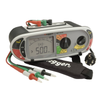
.3 Use the UP and DOWN arrows on the right hand TEST and LOCK buttons to set the tripping current to match that
on the variable RCD.
The tripping current can be selected as below;
10 mA to 50 mA – 1 mA steps
50 mA to 500 mA – 5 mA steps
500 mA to 1000 mA – 10 mA steps
.4 Save this current using the left hand Red LOCK button.
.5 Test using the previous test options above.
8.10 AUTO RCD testing
The AUTO function of the RCD test options automatically performs the 1/2xI, 1xI and 5xI in both 0° and 180°, without touching the
MFT. The operator can stand by the RCD and reset the device each time it trips.
Test sequence in AUTO mode:
To test the RCD in AUTO mode
.1 Select the AUTO range on the left range knob
.2 Select the RCD Type as in section 8.2 above.
.3 Connect the Red (L1) and Green (L2) terminals of the MFT to the RCD as in section 8.3.
.4 Press the TEST button on the MFT. The test sequence as in the table above will be performed.
Each time the RCD trips, it should be reset. The MFT automatically detects the reset and continues testing until the RCD stops
tripping. The MFT will display “END”
.5 Return to the MFT and press the mode <-> button to scroll through the test results in sequence.
8.11 3 Phase RCD testing
The MFT1700 series is designed to test RCDs on 3 phase installations.
To test RCDs in a 3 phase system each RCD is tested as a single RCD, from Phase to earth. As described in section 8.1 to 8.5.
Where no earth is available, the upstream/downstream method can be used. This requires testing across two phases, as below.
.1 To test Phase 1 RCD, connect the MFT Red (L1) terminal to the downstream (o/p) of the RCD to be tested.
RCD Type AC AC - S A A - S B
1/2x I at 0° Y Not available Y Not available Not available
½ x I at 180° Y Y
1 x I at 0° Y Y
1 x I at 180° Y Y
5 x I at 0° Y Y
5 x I at 180° Y Y

 Loading...