15
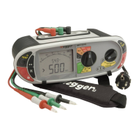
The test mode is displayed as below:
Default mode 1st Press 2nd Press
Note: RCDs can still trip when performing a “non-trip” loop test if there is an existing high level of fault current flowing in the Earth
conductor, or the RCD is not operating within specification.
7.1.2 L-N or L-L circuits:
L-N (or L-L) selected Test performed
7.1.3 Z, Zmax, Zref and R1+R2 (MFT1720 and MFT1730 only)
The right range knob has addition options.
Z - Standard loop impedance measurements
Zmax - For multiple loop measurements where the worst case value is required
Zref - the Ze or Zdb value used when calculating the R1+R2 value
R1+R2 - The loop impedance less the Zref value.
For general loop impedance testing the Z seeing should be selected.
Refer to section 7.5 to 7.7 for additional functionality.
7.2 Making a loop impedance measurement
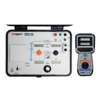
7.2.1 Ze measurements at the origin (Phase to Earth)
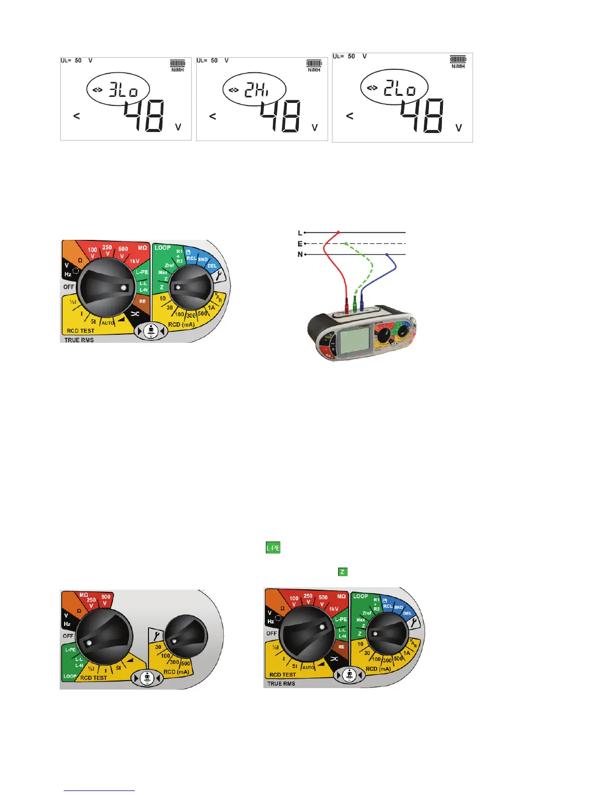
.1 Set the LEFT rotary range knob to the
range.
.2 On the MFT1720 and 1730, set the RIGHT rotary knob to
.
MFT1710 MFT1720 and MFT1730
The MFT automatically uses the Phase and Earth terminals.
.3 Connect test leads as below, with the Red test lead connected to the L1 (Red terminal on the MFT and the Green
test lead connected to the Green (L2) terminal.

 Loading...