MFT1710 MFT1720 and MFT1730
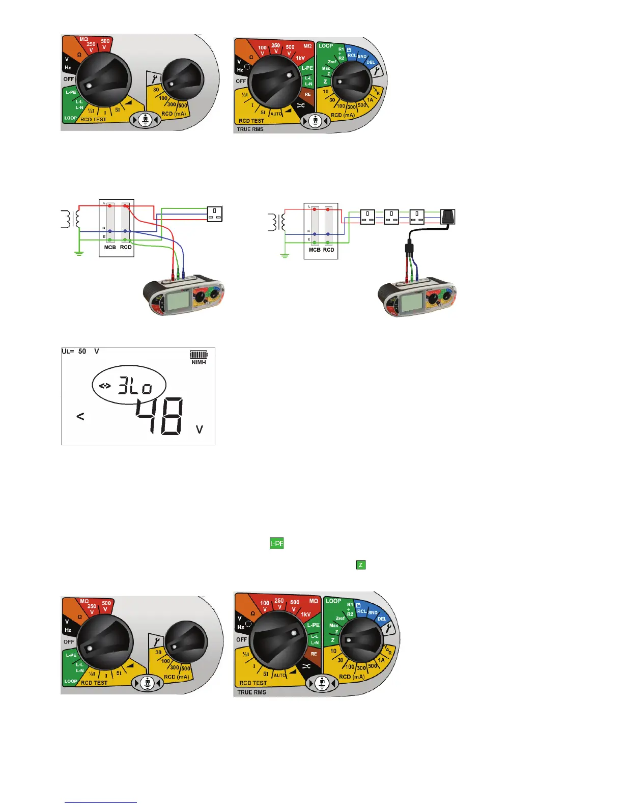
.3 Connect test leads as below, with the Red test lead connected to the L1 (Red terminal on the MFT, the Green test
lead connected to the Green (L2) terminal and the Blue test lead to the Blue (L3) terminal.
.4 Ensure the display is in the “3Lo” mode. If not, press the <-> function button to select “3Lo”.
.5 Press ‘TEST’ to start the test sequence. This can be automated in SETUP so the test starts when contacting the
circuit. See section 10.
.6 On completion of the test, the display will show the loop resistance on the large display segments, and the fault
current on the small display segments.
Using 2 wire measurement – 2Lo
.1 Set the LEFT rotary range knob to the
range.
.2 On the MFT1720 and MFT1730 set the RIGHT rotary knob to
.
MFT1710 MFT1720 and MFT1730
.3 Connect the test leads to the circuit as below, with the Red test lead connected to the L1 (Red terminal on the MFT)
and the Green test lead to the Green (L2) terminal.

 Loading...