1. Safety Information 3
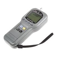
2. The TDR Cable Length Meter 4
3. Controls, Indicators, and Buttons Overview 5
4. Meter Operation 8
4.1 Principles of operation 8
4.2 How to connect a cable to the Meter 8
4.3 How to set the cable type 9
4.3.1 Selecting a library cable type 9
4.3.2 Cable library for 39 standard cable types 10
4.3.3 Testing cables not included in library 12
4.4 How to determine unknown V.O.P settings 14
4.4.1 Expanding cable library
for custom cable types using nonvolatile memory 15
4.5 How to measure cable length 19
4.6 How to check networks (Thin Ethernet) 19
5. Changing the measurement scale between English and Metric 20
6. Measurement accuracy 21
7. Theoretical and actual V.O.P 22
8. Special features 23
8.1 Low battery indication 23
8.2 Overrange indication 23
8.3 Enable or disable the auto-power-off mode 24
8.4 Tone Generator mode 25
8.5 Line Voltage Detection mode 25
9. Maintenance 26
10. Specifications 27
Repair and Warranty
CONTENTS
Safety Warnings
This
Meter c omplies
with the safety requiremen
t
s of IEC 1010-1 : 2001.
I
t is
designed
for
use on de-energized
circui
t
s only, however this Meter
is protec
t
ed
against telephone networking voltages (EN 60950 : 1999 Sec. 2.3). Connection to
any mains supply voltages may result in damage to the Meter and/or a hazard to
the user. Hence the user must assume responsibility for ensuring his or her own
safety.
International Symbols used on the Meter
Caution! Refer to the explanation in this manual.
Double insulation or Reinforced insulation
Battery
Meter complies with current EU Directives.
International Standards
Safety : IEC 1010-1 : 2001
EMC : EN 61326 : 1997
+
A
1
: 1998
1. Safety Information
EMC Standard Category of Pass
ESD IEC 1000-4-2 A
EM IEC 1000-4-3 A
Burst IEC 1000-4-4 A
Surge IEC 1000-4-5 A
Conducted RF IEC 1000-4-6 A
2 3