4.3.3 Testing cables not included in library
If the cable type to be tested is not in the library, it can s
t
ill be
t
ested if
t
he V.O.
P
is
known
.
If the V.O.P is unknown, refer to Sec
t
ion 4.4.
1 . Turn the
Meter on.
2 . The
Meter will display the previously selected cable se
t
ting [see Initial Display of
Sec
t
ion 3.(1)] with i
t
s
V
.O.P.
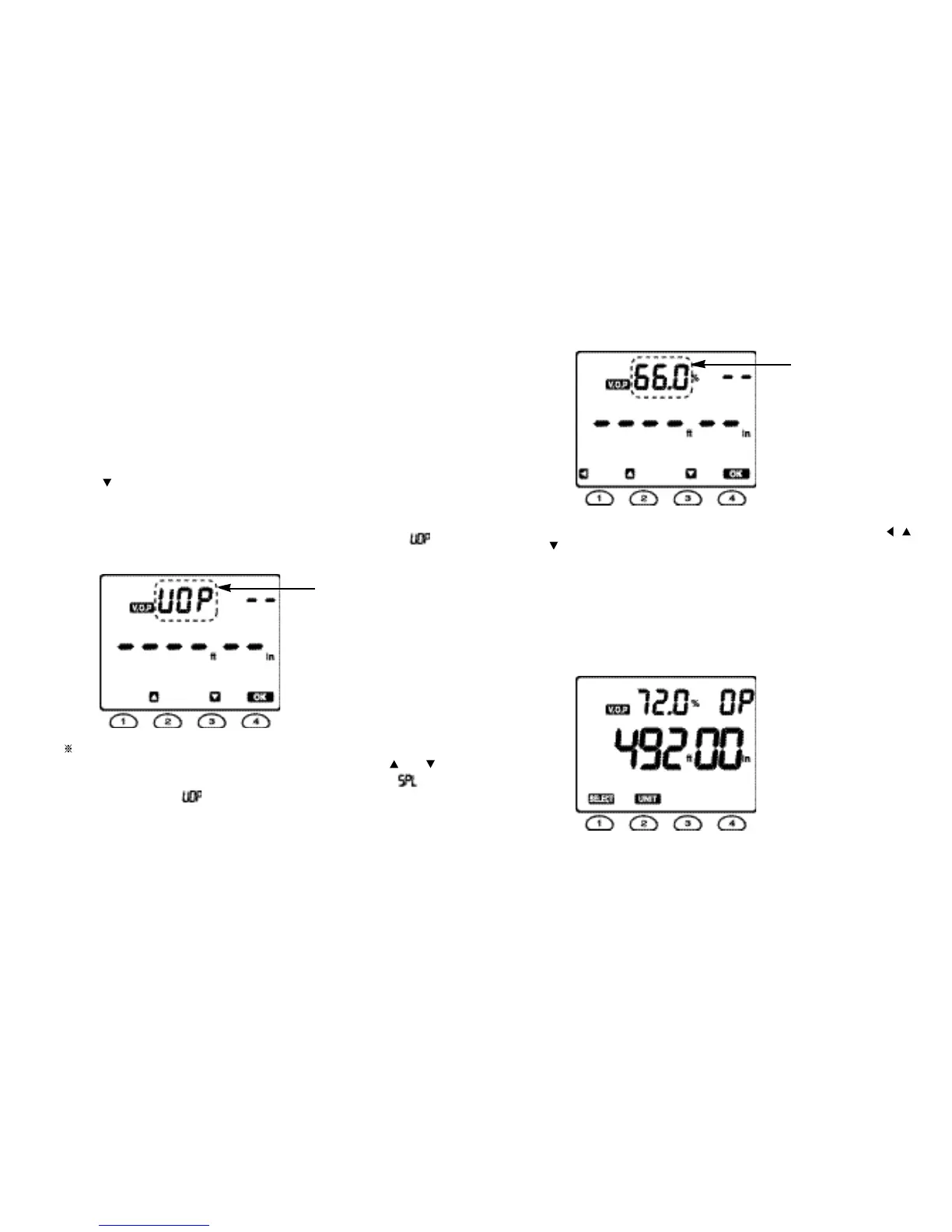
3 . Press the SELECT button then the Meter
will display both the LI
B
RARY symbol
(blinking) and the V.O.
P
symbol (see Fig. 3).
4 . Press the
button then the LIBR
A
RY symbol will stop blinking and the V.O.P
symbol will be blinking.
5 . Press the OK button
t
o set the Meter to the V.O.P
adjusting mode, when the
LIBRARY symbol will disappear, the
V.O.P symbol will stop blinking, and the “ ”
segments will start to
blink.
The Meter can
enter into
the Calibrate Cable function to
determine the
V.O.P for a known length of cable by pressing any button out of and
buttons when the Meter is in the V.O.P adjusting mode. Then, the will
appear replacing the and “ 30.00 ” will be blinking to alert the user that
a sample cable longer than 30 ft (10 m) is necessary.
Fig. 5
6. Press the OK button again then the default V.O.P value of 66.0 % will start to
blink.
7. Scroll through the V.O.P value between 1.0 % and 99.9 % by using the ,
and buttons to find the required V.O.P value.
8 . Press the OK button
t
o set the Meter to the required V
.
O
.
P value.
9 . Connect the cable
to be tested to BNC
connector of the
Meter.
1 0 . Press the TEST button
to take the required measurements.
For example, the Meter can have the following
display
.
Fig. 6
Fig. 7
1312
“ blinking ”
“ blinking ”