(3) MENU (on screen) SELECTION BUTTONS
Each setting of the Meter to a measurement function may activate one or more
menu selection button settings
on the LCD.
Press the corresponding menu
selection button to select the desired measurement.
Setup Mode
Use the menu selection but
t
ons in order to
edit desired se
t
up values as
follows :
(4) POWER ON/OFF BUTTON
Press the POWER button for more than 1 second to turn the Meter on.
Auto-Power-Off
This Meter is completely turned off after 30 minutes of no activities. Press the
POWER
button to turn the Meter on again. This feature can be disabled (refer
to Section 8.).
(5) BACKLIGHT ON/OFF BUTTON or EXIT BUTTON
Press this button for more than 1 second to turn the backlight on and press this
button again for more than 1 second to turn it off.
Press this button momentarily to always return to the initial display when the
meter is in either SELECT mode or Memory mode. And also press the button
momentarily to exit the Tone Generator mode.
(6) MEMORY BUTTON or TONE BUTTON
Press this button momentarily to activate the memory mode. The display shows
three menu selections : STORE, RECALL and CLEAR
.
Press this button for more than 1 second to activate the Tone Generator mode.
(Press the EXIT button to exit the Tone Generator mode.)
(7) TEST BUTTON
Press this but
t
on momentarily to
measure length,
distance to an open or a
short, or V.O.P of cable under test.
(1) DISPLAY
Extra-large backlit (ICON type 7 segment) LCD. When the Meter is turned on,
all display segments and symbols appear briefly (during 1.5 seconds) for a
selftest and then the Meter defaults the following initial display.
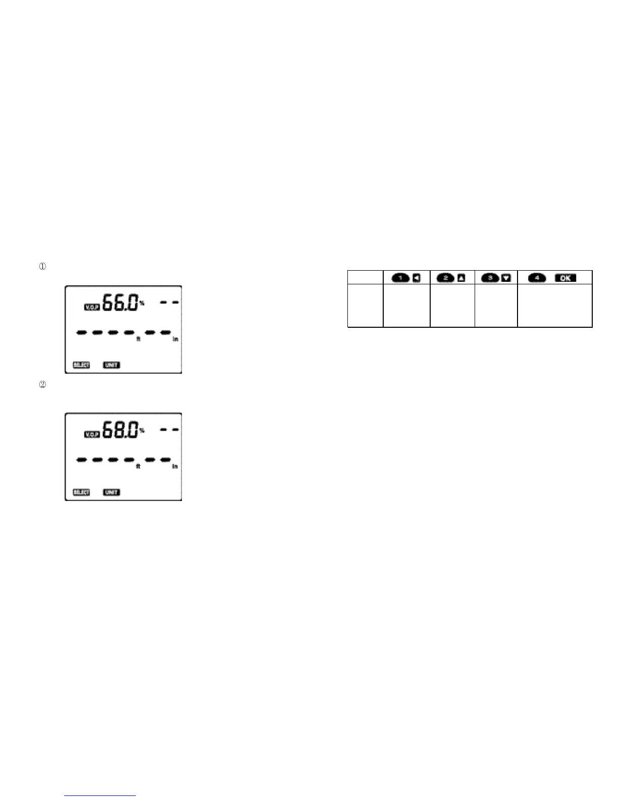
Initial Display
When shipped out of factory
The Meter defaults V.O.P of 66.0 % and English scale.
When turned on after having been used in the field
The Meter defaults the V.O.P (e.g. 68.0 %) having been used just before it
was turned off.
(2) BNC
A shielded connector for either coaxial cable or
A
lligator Clip
adaptor (a
standard accessory).
Fig. 1
Fig. 2
Button
Function
Press to step
to next digit in
setting value.
Press to
increase
setting value.
Press to
decrease
setting value.
Press to move t o next
Setup.
Press to save all settings
and e xit Set up
Mo de
when setting is ended.
76