14
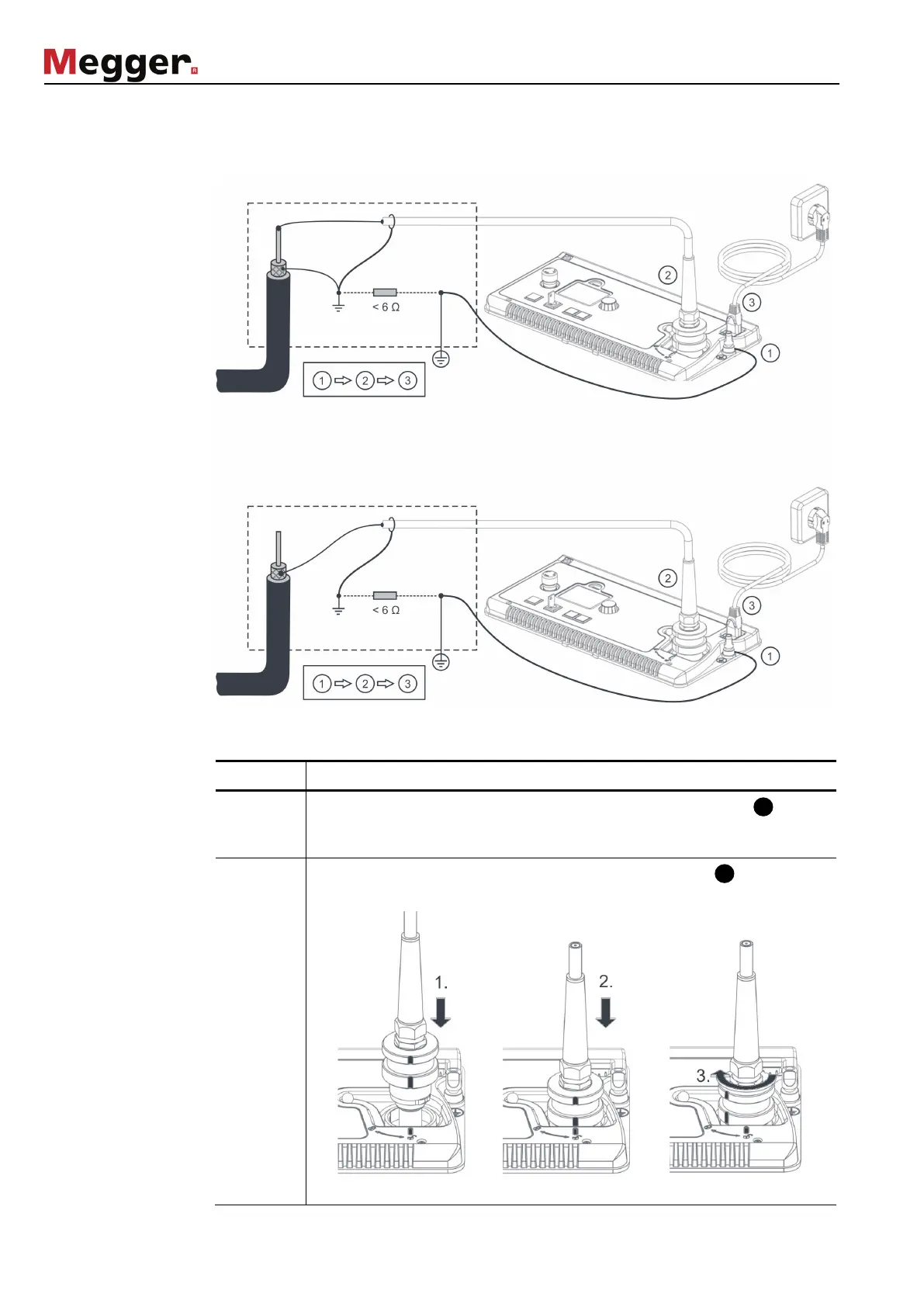
Connection diagram The following figure shows the simplified connection diagram:
Connection sequence
Connect the system in the following order:
Step Action
1
The earthing cable is to be fastened on the earthing connection of the
system and then connected to a suitable point on the protective earthing
system of the station.
2
Attach the high voltage connection cable to the HV output of the
system as shown in the figures below:
110 V … 230 V
-, VLF Sinus or VLF Rectangle mode
Sheath testing and pinpointing
110 V … 230 V
50 / 60 Hz