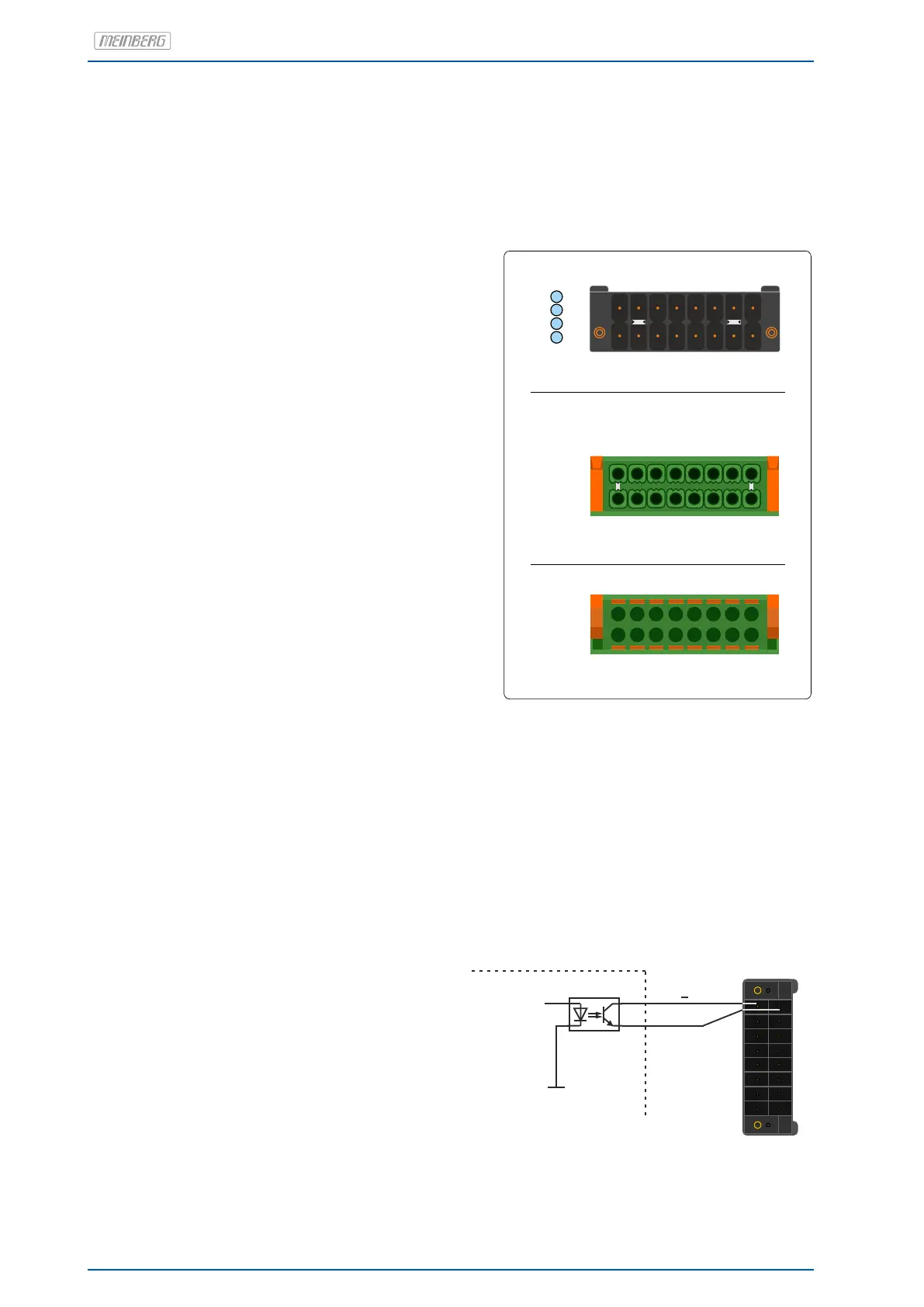
5.10 DMC X2 Terminal Connector
Note: The connector on the device side and the connection socket of the X2 terminal are provided with coding
pins to avoid confusion with the X1 connection terminal.
Pin 1 PP 5+ programmable pulse (optocoupler)
Pin 2 PP 5 programmable pulse (RS-422A)
Pin 3 PP 5 programmable pulse (RS-422B)
Pin 4 PP 6 programmable pulse (RS-422A)
Pin 5 PP 6 programmable pulse (RS-422B)
Pin 6 + TC In Time Code DCLS (TTL, isolated)
Pin 7 + TCA* Out Time Code DCLS (TTL, isolated)
Pin 8 - TCA Out Time Code DCLS (TTL, isolated)
TTL active high 250mA,
short circuit proof
* TCA = Time Code Amplified, DCLS output
with large output current.
Pin 9 PP 5- program. pulse (optocoupler)
Pin 10 GND ground
Pin 11 GND ground
Pin 12 GND ground
Pin 13 GND ground
Pin 14 - TC In Time Code DCLS (TTL, isolated)
Pin 15 not used
Pin 16 not used
Status-LEDs:
PP 5 . . . PP 8 Status of Pulses Out
Status
PP
9
8
16
1
X1
9
8
16X2
1
9
8
16
1
5
6
7
8
To the X2 device connection
16-pin socket with retaining clip
Cable inlet side
Scheme Terminal assignment
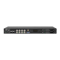
Programmable output PP 5
DC-insulated by optocouplers
U
CEmax
= 55 V
I
Cmax
= 50 mA
P
tot
= 150 mW
Response time
Turn on Time: typ. 5µs, max. 9µs
Turn off Time: typ. 10µs, max. 70µs
Standard (Opto Coupler)
Channel 5
PP 5
PP 5 +
Pulse generator
1
8
16
9
22 Date: 17th June 2020 microSync