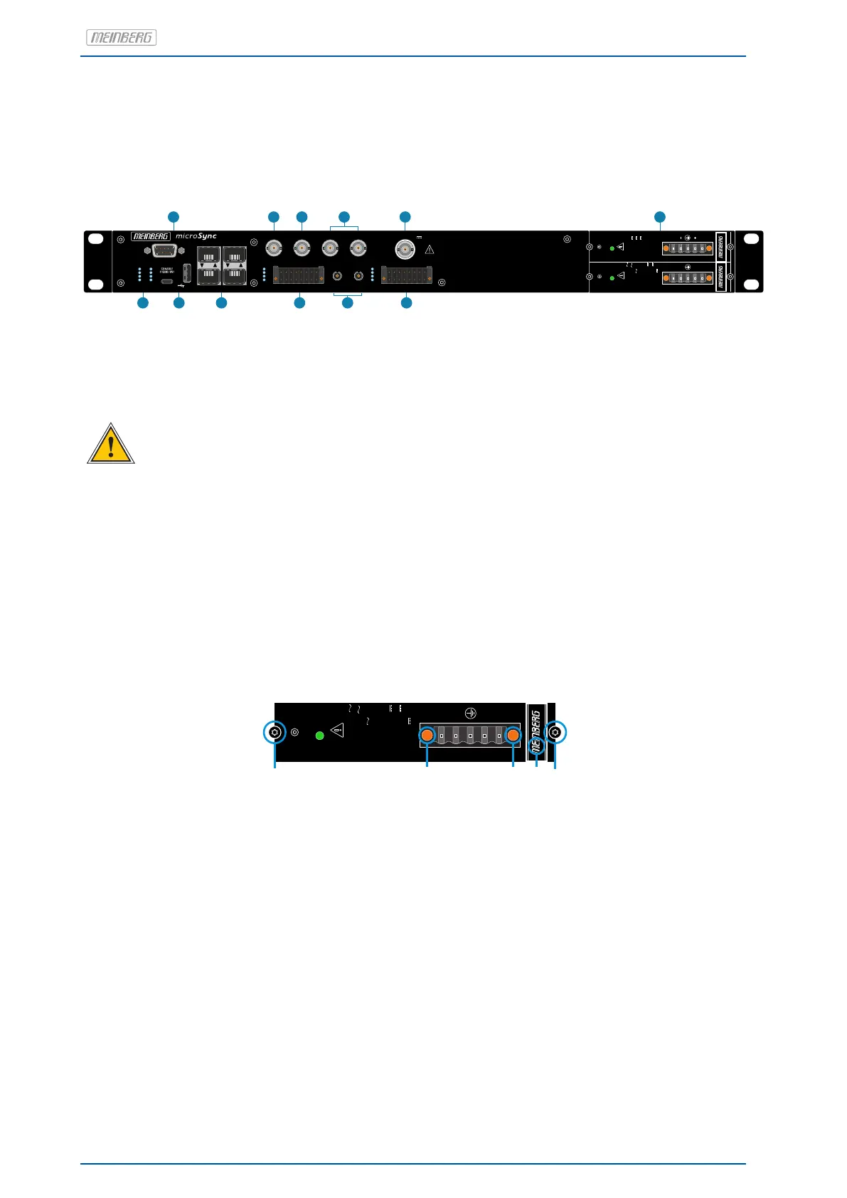
5 microSync RX101/AD10DC20 Connectors
COM 0
LAN 0 LAN 2
LAN 1 LAN 3
F-Synth Out TC AM Out PP 1 Out PP 2 Out
PP 7 PP 8
Fiber Optic Out
X1X2
1
9
8
16
1
9
8
16
RX
Antenna
GNSS | IF | 15 V
1
4
5
6
7
10
8
9
3
12
N/-
L/+
AD10MS
Power
U = 100 V - 240 V
N
U = 90 V - 254 V
max
I = 1.0A
N
f = 50 - 60Hz
N
U = 100 V - 200 V
N
U = 90 V - 240 V
max
I = 0.6A
N
N/-
L/+
AD10MS
Power
U = 100 V - 240 V
N
U = 90 V - 254 V
max
I = 1.0A
N
f = 50 - 60Hz
N
U = 100 V - 200 V
N
U = 90 V - 240 V
max
I = 0.6A
N
2
11
U = 24 - 48 V
N
U = 20 - 60 V
max
I = 2.10 A
N
Power
DC20MS
Fail
R
CPU REC
T
N
A
Ant
Nav
Init
5
Status
PP
6
7
8
1
Status
PP
2
3
4
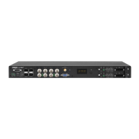
5.1 AC/DC Power Supply
Hotplug
It is possible to remove or install power supplies from the system housing during operation.
Required Tools
• Slot screwdriver 0.4mm thick, 2,5mm wide
• Screwdriver Torx TR8x60
Hints for Hot-Plug compatible Power Supplies
Replacing the power supply unit
N/-
L/+
AD10MS
Power
U = 100 V - 240 V
N
U = 90 V - 254 V
max
I = 1.0A
N
f = 50 - 60Hz
N
U = 100 V - 200 V
N
U = 90 V - 240 V
max
I = 0.6A
N
N/-
L/+
AD10MS
Power
U = 100 V - 240 V
N
U = 90 V - 254 V
max
I = 1.0A
N
f = 50 - 60Hz
N
U = 100 V - 200 V
N
U = 90 V - 240 V
max
I = 0.6A
N
A A
B
B
C
1. Interrupt the power supply of the power supply unit by pulling off the protective plug of the power cable.
2. Remove the 5-pin DFK-jack from the power supply after dissolving the two clamping screws (B) with the
slot screwdriver.
3. Then loosen the two Torx screws (A) of the power supply that needs to be replaced with the Torx screwdriver (TR8).
4. The dissolved power supply can be removed with the handle (C) now.
5. Put the new power supply in the free slot and secure it with the two previously dissolved Torx
fastening screws (A).
6. Connect the 5-pin DFK jack of the power cable to the power supply and put the two slit screws (B) back on.
7. The protective contact plug of the power cable can be reconnected to the power supply.
8. The LED of the new power supply should now light up. Furthermore, the status Power Supply "green" should
be displayed in the Status System menu of the Meinberg Device Manager.
The status LED of the new power supply should now light up. The "OK" status must be displayed in the system’s
web interface.
14 Date: 17th June 2020 microSync