5 microSync RX101/AD10DC20 Connectors
Scheme Terminal assignment
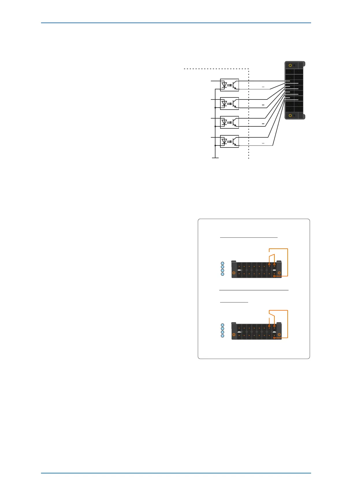
Programmable Pulses
Four programmable outputs (PP 1 - PP 4)
DC-insulated by optocouplers
U
CEmax
= 55 V
I
Cmax
= 50 mA
P
tot
= 150 mW
Response time
Turn on Time: typ. 5µs, max. 9µs
Turn off Time: typ. 10µs, max. 70µs
Standard (Opto Coupler)
Channel 4
Channel 2
Channel 1
PP 4
PP 2
PP 1
PP 3 +
PP 1 +
Pulse generator
PP 2 +
1
8
16
9
Channel 3
PP 3
PP 4 +
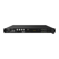
Error Relay
The X1 connector has a potential-free contact which is
controlled directly by the used reference clock (GPS,
GNS, GNS-UC). Normally, when the reference clock
has synchronized, the the relay contact "NO" switch to
active. If the reception is disturbed or the device is
switched off, the relay contact "NC" is active.
Technical Specification
Switching Voltage max: 60 V DC
Switching Current max: I
max
: 400mA
Switching Load max: 24 W
Response Time: ca.2ms
Status
PP
X1
X1
1
2
3
4
Normal Operation Mode:
(normally closed)
CO - NO connected
NO
NC
CO
Error Mode:
(normally open)
CO - NC connected
Status
PP
X1
X1
1
2
3
4
NO
NC
CO
microSync Date: 17th June 2020 25