3. Remove two M4 x 16 screws securing the sensor and remove the sensor.
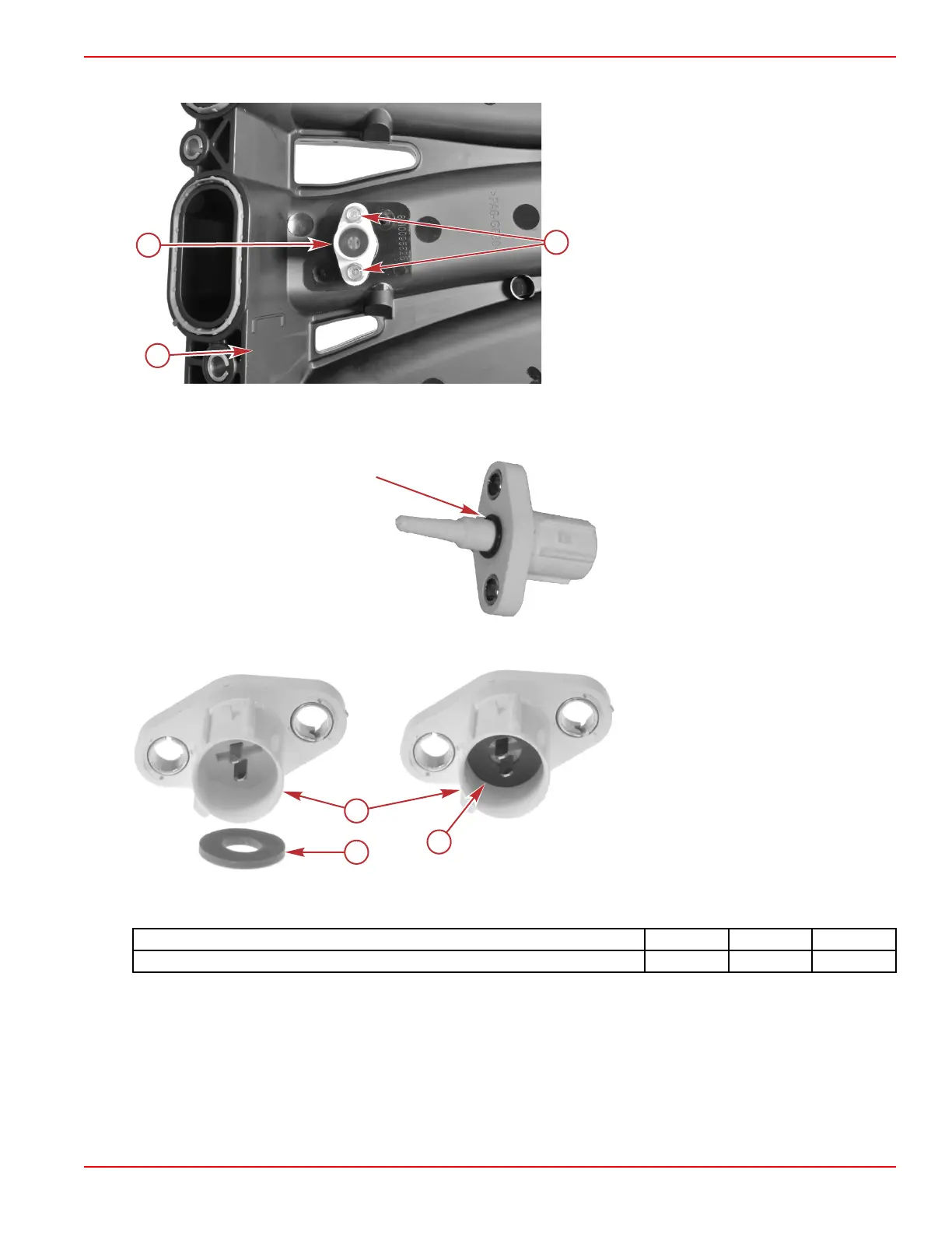
a - Starboard air intake runner
b - IAT sensor
c - M4 x 16 screws (2)
IAT Sensor Installation
1. Install a new O‑ring onto the IAT sensor.
2. Ensure that the gasket is installed in the IAT sensor connector.
a - IAT sensor connector
b - Gasket
c - Gasket installed in the IAT sensor
connector
NOTE: The IAT sensor does not come with a gasket. It must be ordered separately.
3. Install the sensor into the starboard intake runner. Tighten the M4 x 16 screws to the specified torque.
Description
Nm lb‑in. lb‑ft
M4 x 16 screw 1.7 15 –
4. Connect the engine harness to the sensor.
IMPORTANT: The intake runner fasteners must be tightened to the specified torque in the specified order. Refer to the
appropriate service manual.
5. Install the starboard air intake runner. Refer to the appropriate service manual.
Sensors
90-8M0146617 eng JULY 2018 © 2018 Mercury Marine Page 5A-25
 Loading...


