EasyManuals Logo

Mercury V6 200 User Manual

Mercury V6 200
302 pages
To Next Page IconTo Next Page
To Previous Page IconTo Previous Page
Page #228 background imageLoading...
Page #228 background image
Key Position Continuity should be indicated at the following points:
Accessories A C
Run A D
Start
A F
F D
A D
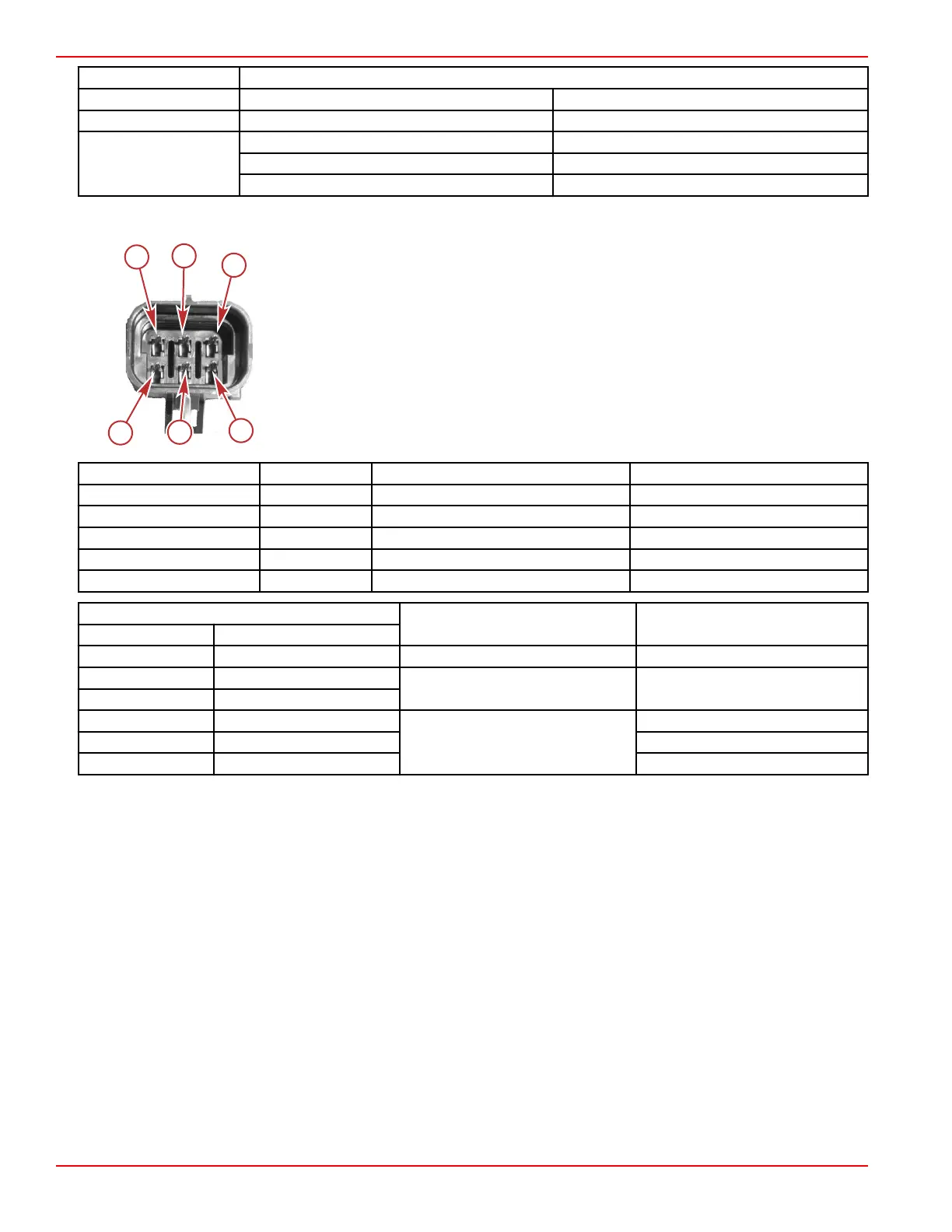
Key Switch Test (Three Position)
a - Pin A
b - Pin B
c - Pin C
d - Pin D
e - Pin E
f - Pin F
Ref. No. Pin Wire Color Description
a A Red 12 volts
b B Black Ground
c, d C, D Purple Run
e E Black/yellow Off
f F Yellow/red Start
Meter Test Leads
Key Position Reading (Ω)
Red Black
Pin B Pin E Off Continuity
Pin A Pin F
Run Continuity
Pin A Pin C, D
Pin A Pin F
Start
Continuity
Pin F Pin C, D Continuity
Pin A Pin C, D Continuity
b
c
d
e
f
a
18868
Charging and Starting System
Page 6B-14 © 2018 Mercury Marine 90-8M0146617 eng JULY 2018

Table of Contents

Questions and Answers:

Question and Answer IconNeed help?

Do you have a question about the Mercury V6 200 and is the answer not in the manual?

Mercury V6 200 Specifications

General IconGeneral
Engine TypeV6
Horsepower200 hp
Fuel Induction SystemElectronic Fuel Injection (EFI)
SteeringBig Tiller; Dual cable mechanical; Electro-hydraulic power steering; Hydraulic power steering
Gear Ratio1.85:1
Shaft Length20"; 25"
StartingElectric
Alternator Output60 amps
Weight505 lbs (20")

Related product manuals