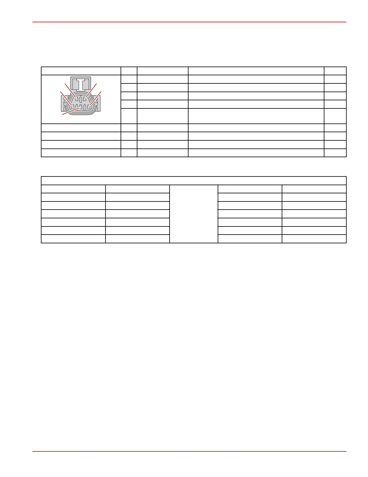
a - Propulsion control module (PCM), connector A
b - Main power relay
c - Hot stud
d - Engine fuses
e - Coil harness connector
f - Ignition coil adapter harness
g - Coil A connector (cylinders 1 and 4)
h - Coil C connector (cylinders 3 and 6)
i - Coil B connector (cylinders 2 and 5)
Connector Pin Wire Color Function PCM
A Green/brown Coil A AH4
B Green/red Coil B AH3
C Green/purple Coil C AH2
D N/A Not used –
E Red/yellow Fused (20 A) 12 V power (+) –
Hot stud ring terminal – Red 12 V battery power (+) –
MPR 86 Yellow/purple Main power relay (MPR) control signal AA2
MPR 87 Red/white Switched 12 V power (+) –
Ignition coil B A Red Fused (20 A) 12 V power (+) –
Wire Color Code Abbreviations
Wire Color Abbreviations
BLK Black
BLU Blue
BRN Brown GRY or GRA Gray
GRN Green ORN or ORG Orange
PNK Pink PPL or PUR Purple
RED Red TAN Tan
WHT White YEL Yellow
LT or LIT Light DK or DRK Dark
Ignition
90-8M0146617 eng JULY 2018 © 2018 Mercury Marine Page 6A-5
 Loading...


