EasyManuals Logo

Mercury V6 200 User Manual

Mercury V6 200
302 pages
To Next Page IconTo Next Page
To Previous Page IconTo Previous Page
Page #283 background imageLoading...
Page #283 background image
a - PCM connector A
b - PCM connector B
c - PCM connector C
d - Clean power connector
e - 14‑pin connector
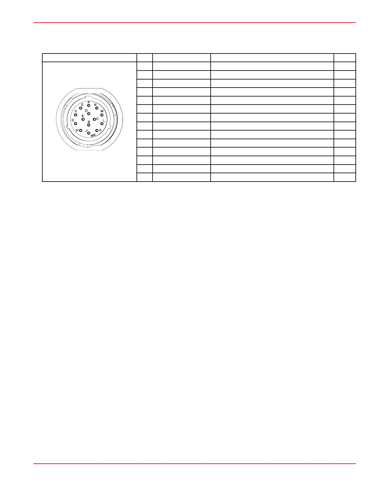
Connector Pin Wire Color Function PCM
53467
A Red/black 12 V clean power (+) –
B Black Clean power ground (–) –
C Purple 12 V wake circuit (+) CC1
D Black/yellow E‑stop signal AD3
E Blue/yellow Oil pressure analog gauge BL3
F White CAN P high BG2
G Blue CAN P low BG1
H Light blue/white Trim up command CC2
J Green/white Trim down command CC3
K Orange/green Trim position analog gauge CA3
L Tan/light blue Horn AA4
M Gray Tachometer signal AA1
N Yellow/red Start/stop signal CA2
P Brown Coolant temperature analog gauge CD1
SmartCraft Circuit Diagrams
90-8M0146617 eng JULY 2018 © 2018 Mercury Marine Page 8A-5

Table of Contents

Questions and Answers:

Question and Answer IconNeed help?

Do you have a question about the Mercury V6 200 and is the answer not in the manual?

Mercury V6 200 Specifications

General IconGeneral
Engine TypeV6
Horsepower200 hp
Fuel Induction SystemElectronic Fuel Injection (EFI)
SteeringBig Tiller; Dual cable mechanical; Electro-hydraulic power steering; Hydraulic power steering
Gear Ratio1.85:1
Shaft Length20"; 25"
StartingElectric
Alternator Output60 amps
Weight505 lbs (20")

Related product manuals