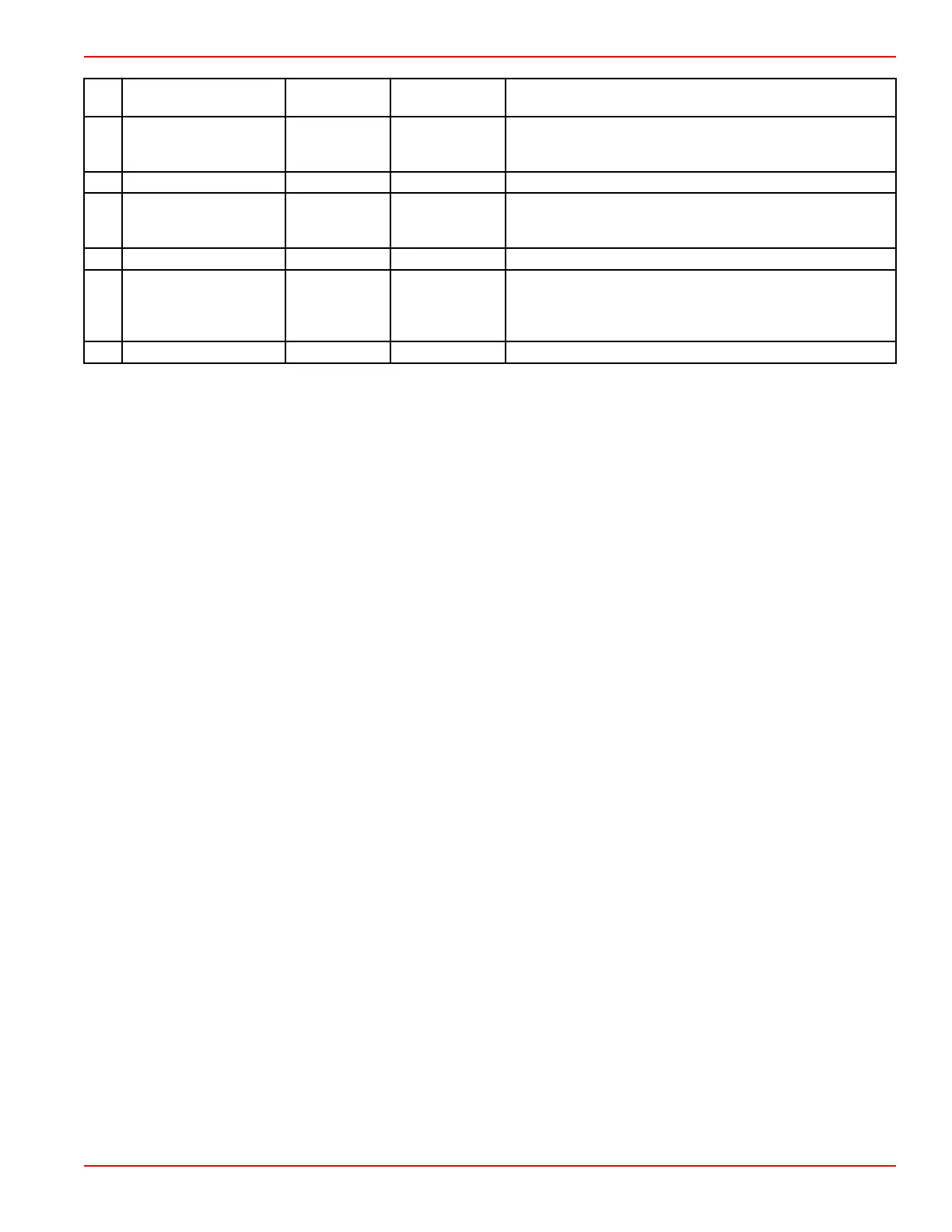
Pin Function Wire Color
Application
Notes
Description
CC4
Fuel level 1 sensor
signal
Pink/black –
Circuit is designed to read low resistance sensors, typically
between 0 and 200 ohms. Uses standard fuel tank sending
units.
CD4 Not used – – –
CE4 Sensor power C Purple/black –
Dedicated 5 V positive power supply for transom and hull
sensors. Maintains 5 V regardless of battery voltage
fluctuations.
CF4 Not used – – –
CG4 Driver power 2 Red/blue –
12 V power supply from the battery, through the main power
relay (MPR) and through the PCM 112. The PCM controls
the MPR through pin AA2. This power is used for high
current actuators.
CH4 Shift actuator A (+) Red/purple – –
PCM 112 Important Information and Pinouts
90-8M0146617 eng JULY 2018 © 2018 Mercury Marine Page 2A-11
 Loading...


