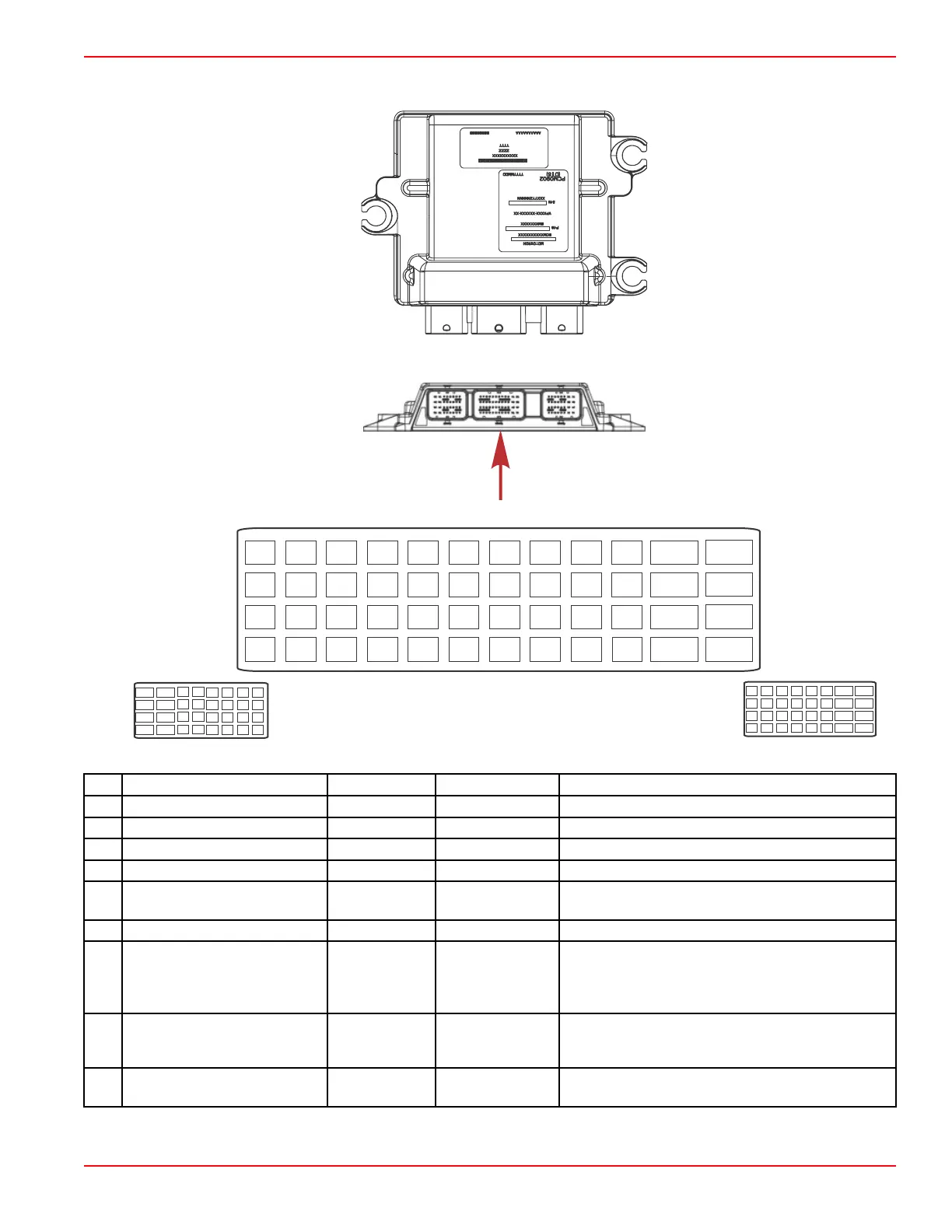
Connector B
C1A
C1B
C1C
C1D
C1E
C1F
C1G
C1H
C2A
C2B
C2C
C2D
C2E
C2F
C2G
C2H
C3A
C3B
C3C
C3D
C3E
C3F
C3G
C3H
C4A
C4B
C4C
C4D
C4E
C4F
C4G
C4H
A
A1A A1B
A1C A1D A1E A1F
A1G
A1H
A2A A2B
A2C A2D A2E A2F A2G
A2H
A3A A3B
A3C A3D A3E A3F A3G
A3H
A4A
A4B
A4C A4D A4E A4F A4G
A4H
BA1
BB1
BC1 BD1 BE1 BF1 BG1 BH1 BJ1 BK1
BL1
BM1
BA2
BB2
BC2
BD2 BE2 BF2 BG2 BH2 BJ2 BK2
BL2
BM2
BA3 BB3
BC3 BD3 BE3 BF3 BG3
BH3
BJ3
BK3
BL3
BM3
BA4 BB4
BC4
BD4
BE4
BF4 BG4 BH4 BJ4
BL4
BM4
BK4
B
C
57215
Pin Function Wire Color Application Notes Description
BA1 Not used – – –
BB1 UEGO (S1) O2 sensor White/gray – Connects to pin 1 of the O2 connector.
BC1 Shift position sensor 2 Pink – –
BD1 Oil level sensor Tan/black – –
BE1
Exhaust gas temperature
(EGT) sensor signal
Brown/white –
2‑wire thermistor. Resistance increases as
temperature decreases.
BF1 Not used – – –
BG1 CAN P (propulsion data)—low Blue –
CAN P bus carries dashboard gauge data and
backup digital throttle and shift commands. These
circuits require both high and low sides to operate.
This is the low (negative) side.
BH1 CAN X (DTS commands)—low Brown –
CAN X bus carries primary digital throttle and shift
commands. These circuits require both high and low
sides to operate. This is the low (negative) side.
BJ1
Throttle demand sensor
position 1
Gray/green
Not used on DTS
engines
–
PCM 112 Important Information and Pinouts
90-8M0146617 eng JULY 2018 © 2018 Mercury Marine Page 2A-7
 Loading...