Section 4
Assembly and Installation
Copyright 2002 Maintenance Manual MM-0230
Page 26 ArvinMeritor, Inc. Issued 07-02
6. Adjust the backlash of the ring gear within the
specification range to move the contact
patterns to the correct location in the length of
the gear teeth. Refer to Ring Gear Backlash in
this section.
A. Decrease backlash to move the contact
patterns toward the toe of the ring gear
teeth. Figure 4.29.
B. Increase backlash to move the contact
patterns toward the heel of the ring gear
teeth. Figure 4.30.
C. Repeat Steps 2-4 and 6 until the contact
patterns are at the correct location in the
length of the gear teeth.
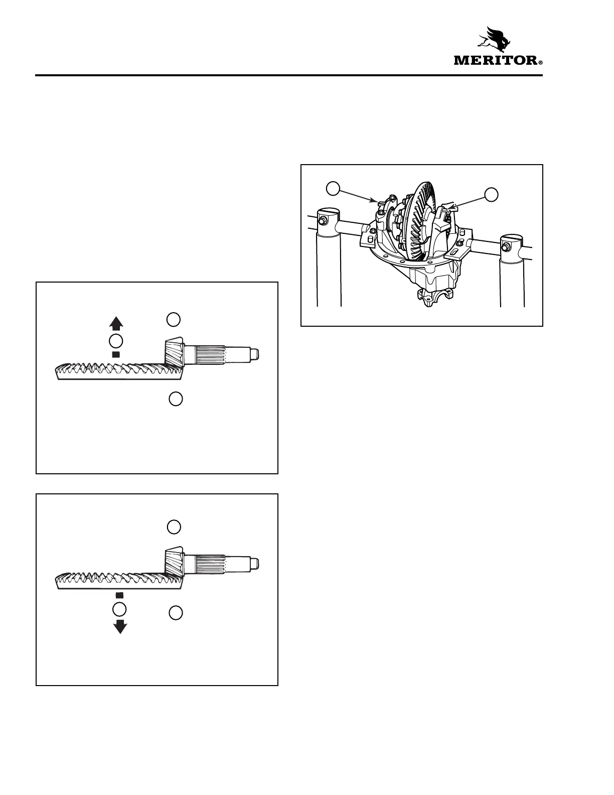
7. Install the cotter pins into the adjusting rings
so that the large end is between the adjusting
ring lugs. Bend the tabs out flat against the
outboard side of the leg caps in two places.
Figure 4.31.
Figure 4.29
1 Move pattern toward toe, loosen adjusting ring this
side.
2 Decrease backlash.
3 Tighten adjusting ring.
Figure 4.30
1 Move pattern toward toe, loosen adjusting ring this
side.
2 Decrease backlash.
3 Loosen adjusting ring.
1
2
3
1003103b
1
2
3
Figure 4.31
1 COTTER PINS
1
1